
Intelligent reflector shift matrix design method

A design method and matrix technology, applied in geometric CAD and other directions, can solve the problems that the IRS optimal phase shift matrix does not have universality, cannot solve the IRS optimal phase shift, and the complexity of calculation cannot be guaranteed, so as to reduce the solution Effects of complexity, faster solution, and reduced numbers

Active Publication Date: 2021-06-25
SHENZHEN INST OF ADVANCED TECH CHINESE ACAD OF SCI
View PDF3 Cites 5 Cited by
  • Summary
  • Abstract
  • Description
  • Claims
  • Application Information

AI Technical Summary

Problems solved by technology

[0006] The optimal phase shift matrix solution method based on optimization problems proposed by literature [1] and literature [2] generally has relatively good performance, but this method is not a panacea , on the one hand, if the proposed optimization problem cannot be converted from a non-convex optimization problem to a convex problem, it means that the proposed optimization problem cannot be solved, and the optimal phase shift of the IRS cannot be solved, but whether the non-convex optimization problem can be converted into a convex optimization problem The problem depends on the researcher's optimization experience
On the other hand, not only is it difficult to transform non-convex problems into convex problems, but the solution process of non-convex optimization is usually cumbersome. For example, using iterative methods, the computational complexity cannot be guaranteed; Optimization results are difficult to converge
Therefore, using this method to solve the IRS optimal phase shift matrix is ​​not universal

Method used

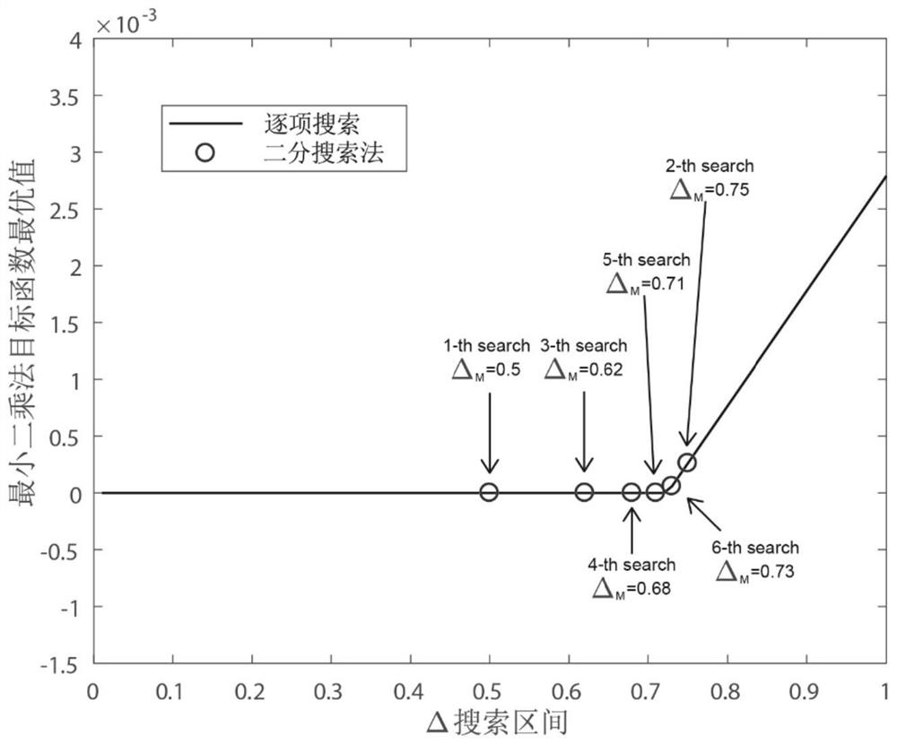
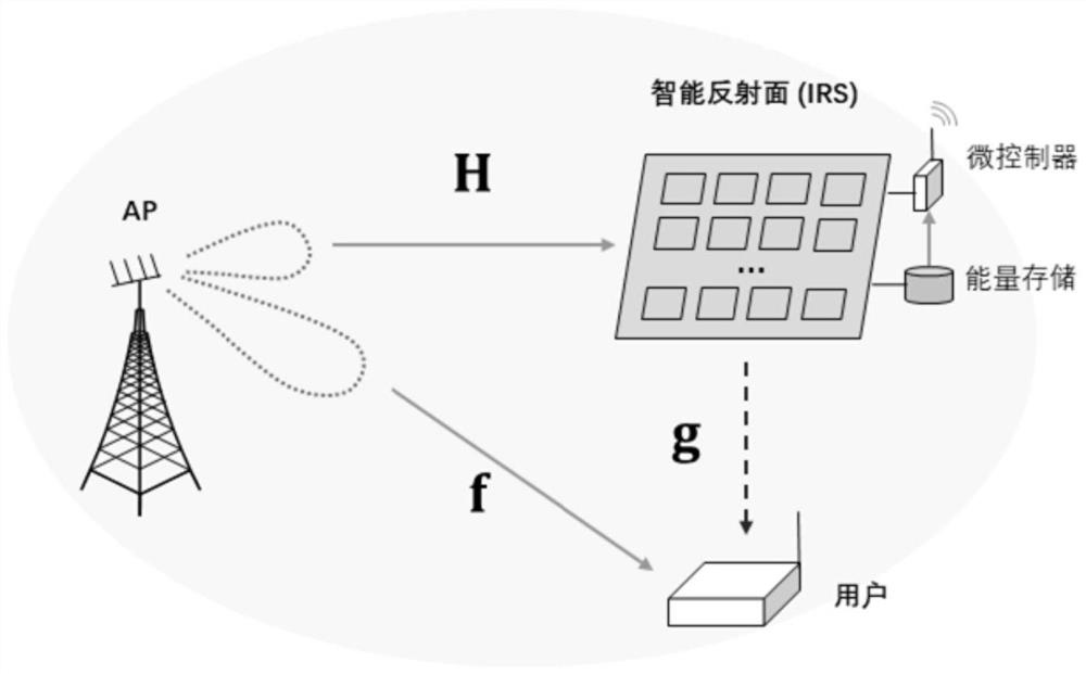
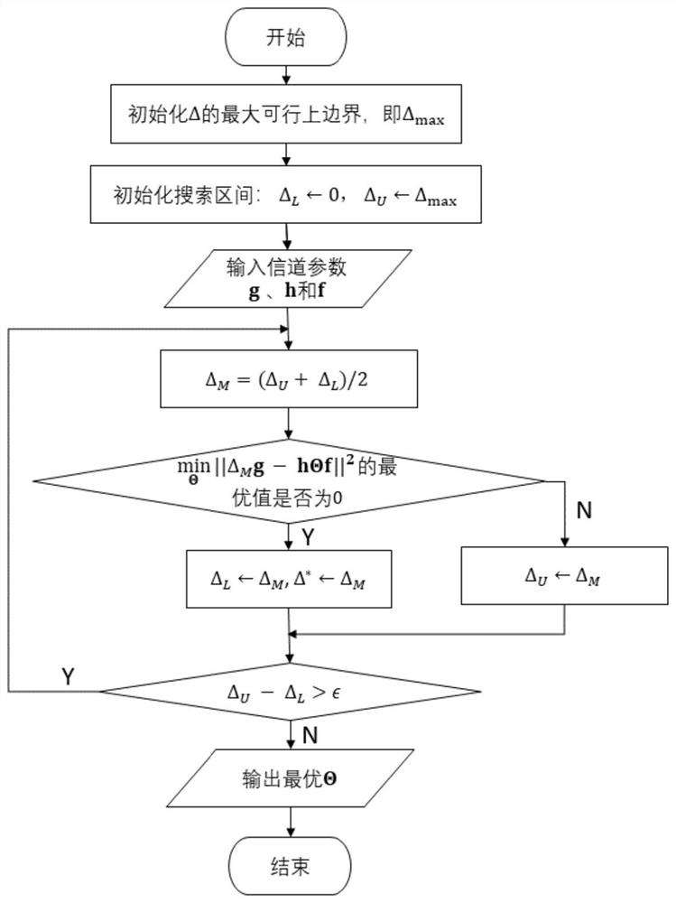

Image

  • Intelligent reflector shift matrix design method
  • Intelligent reflector shift matrix design method
  • Intelligent reflector shift matrix design method

Examples


Embodiment Construction

[0041]In order to make the purpose, technical solutions and advantages of the embodiments of the present invention clearer, the technical solutions in the embodiments of the present invention will be clearly and completely described below in conjunction with the accompanying drawings in the embodiments of the present invention. Obviously, the described embodiments It is some embodiments of the present invention, but not all of them. Based on the implementation manners in the present invention, all other implementation manners obtained by persons of ordinary skill in the art without making creative efforts belong to the scope of protection of the present invention. Accordingly, the following detailed description of the embodiments of the invention provided in the accompanying drawings is not intended to limit the scope of the claimed invention, but merely represents selected embodiments of the invention.

[0042] This method takes the phase shift matrix of the intelligent refle...


PUM


Abstract

The invention relates to an intelligent reflector shift matrix design method, which comprises the following steps of: (1) introducing a positive scalar delta for expressing an equivalent relation of amplitudes between a direct path signal and a reflection path signal; and (2) according to the equivalence relation, designing an IRS optimal phase shift matrix solving criterion based on a least square method. The method for solving the IRS optimal phase shift matrix has application universality, the solving result is only related to channel state information and is irrelevant to IRS scenes and optimization problems, the IRS optimal phase shift matrix can be designed according to the method as long as the channel state information can be accurately estimated, and the method can be applied to a wireless communication system and can also be widely applied to communication systems for wireless energy transmission, wireless information and energy transmission, communication based on the unmanned aerial vehicle and the like.

Description

technical field [0001] The invention belongs to the field of wireless communication, and relates to a design method of an intelligent reflection surface phase shift matrix. Background technique [0002] With the rapid development of mobile communication technology and Internet of Things technology, the number of mobile devices and Internet of Things devices has exploded, and spectrum resources have become increasingly tight. Intelligent reflecting surface (Intelligent Reflecting Surface, IRS) is an emerging technology, which is not only expected to solve the problem of the surge in the number of wireless communication devices in the future, but also can reduce the energy consumption of wireless Internet of Things systems. In addition, the most important advantage of the wireless communication system based on IRS enhancement is that it can greatly increase the channel capacity of users without occupying additional spectrum resources. [0003] IRS consists of a microcontrolle...

Claims


Application Information

Patent Timeline
IPC IPC(8): G06F30/18
Inventor 刘洋谢雨彤龚世民汪漪刘毅肖钟凯
Owner SHENZHEN INST OF ADVANCED TECH CHINESE ACAD OF SCI
Learn More