Battery pack lower shell and battery pack with same
A shell and battery technology, applied in the direction of batteries, battery pack components, circuits, etc., can solve the problems of poor stability, insufficient strength and rigidity, etc., and achieve the effects of stable position, small space occupation, and high structural strength
- Summary
- Abstract
- Description
- Claims
- Application Information
AI Technical Summary
Problems solved by technology
Method used
Image
Examples
Embodiment 1
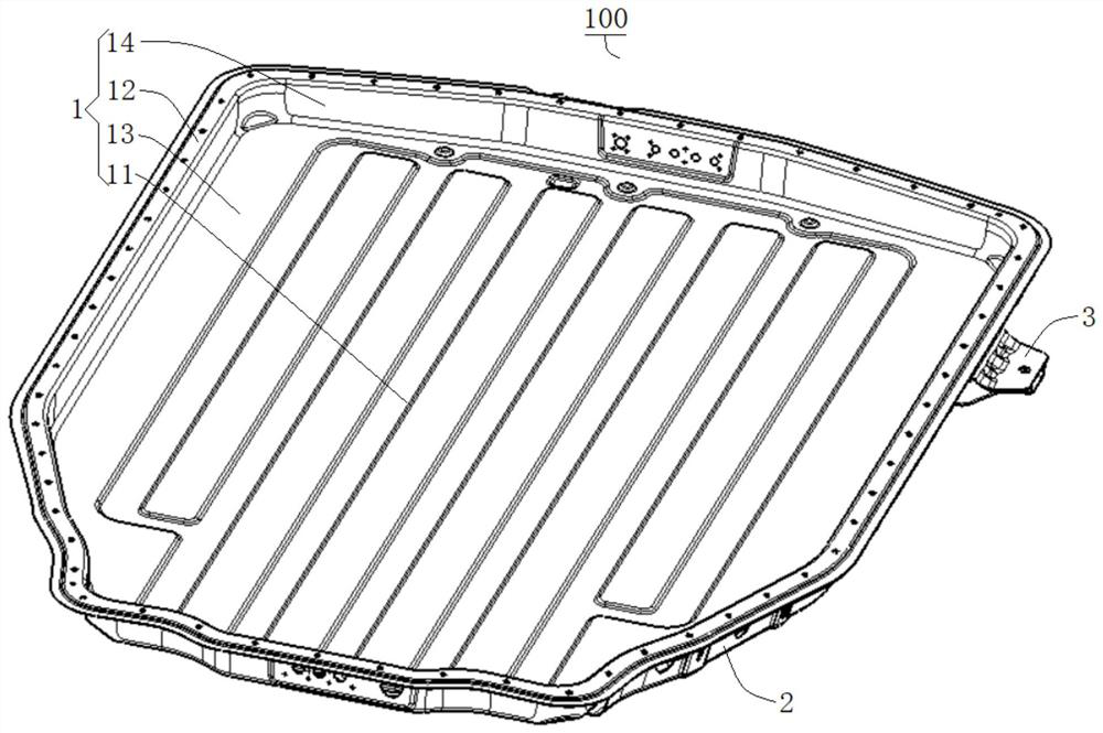
[0112] A battery pack lower casing 100, such as image 3 and Figure 4 As shown, it includes: a lower housing part 1 , a reinforcing part 2 and a fixing part 3 .
[0113] Among them, such as image 3 As shown, the lower casing part 1 is provided with a battery cavity 11 for accommodating batteries, and the lower casing part 1 extends away from the battery cavity 11 to form a first flange 12 .
[0114] like image 3 and Figure 4 As shown, the reinforcing part 2 is connected to the side of the lower case part 1 away from the battery cavity 11, and the cavity 4 is enclosed between the reinforcing part 2 and the lower case part 1 (the specific structure of the cavity 4 can be found in Image 6 ).
[0115] combine Figure 4 and Image 6 As shown, the fixing part 3 is connected between the first flange 12 and the reinforcement part 2 , one end of the fixing part 3 extends into the cavity 4 , and the other end of the fixing part 3 is arranged outside the cavity 4 .
Embodiment 2
[0117] A battery pack lower casing 100, on the basis of Embodiment 1, such as Figure 4 As shown, at least one avoidance channel 21 is provided on the side of the reinforcing part 2 facing the first flange 12 , and each avoidance channel 21 is positioned for a fixing part 3 , and the avoiding channel 21 is connected to the fixing part 3 by spot welding.
[0118] The depth of the avoidance passage 21 is consistent with the thickness of the fixing part 3 , and one end of the escape passage 21 communicates with the cavity 4 .
Embodiment 3
[0120] A battery pack lower casing 100, on the basis of Embodiment 1, such as Image 6 As shown, the fixing portion 3 includes a first extension portion 31 , a second extension portion 32 and a third extension portion 33 in a stepped shape.
[0121] Among them, such as Image 6 As shown, the two ends of the second extension part 32 are respectively connected with the first extension part 31 and the third extension part 33, the first extension part 31 protrudes into the cavity 4 and abuts against the lower housing part 1, the second extension part The opposite side surfaces of 32 are respectively welded to the first flange 12 and the reinforcing part 2 .
[0122] like Figure 4 and Figure 5 As shown, a mounting hole 331 is formed on the third extension portion 33 for connecting with the vehicle body.
PUM
| Property | Measurement | Unit |
|---|---|---|
| thickness | aaaaa | aaaaa |
Abstract
Description
Claims
Application Information
 - R&D
- Intellectual Property
- Life Sciences
- Materials
- Tech Scout
- Unparalleled Data Quality
- Higher Quality Content
- 60% Fewer Hallucinations
Browse by: Latest US Patents, China's latest patents, Technical Efficacy Thesaurus, Application Domain, Technology Topic, Popular Technical Reports.
© 2025 PatSnap. All rights reserved.Legal|Privacy policy|Modern Slavery Act Transparency Statement|Sitemap|About US| Contact US: help@patsnap.com


