
MIMO array antenna beam optimization device and method based on antenna dummy elements

An array antenna and beam optimization technology, which is applied to antenna arrays, antennas, antenna components, etc., can solve the problems of performance degradation and low profile, and achieve the effect of low profile, easy processing, and meeting the needs of integrated integration

Active Publication Date: 2021-06-25
AEROSPACE INFORMATION RES INST CAS
View PDF18 Cites 3 Cited by
  • Summary
  • Abstract
  • Description
  • Claims
  • Application Information

AI Technical Summary

Problems solved by technology

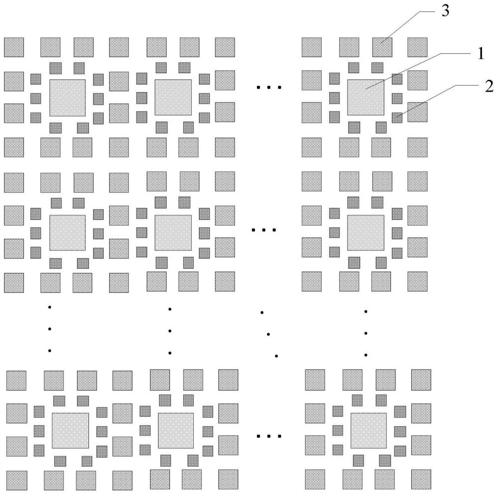
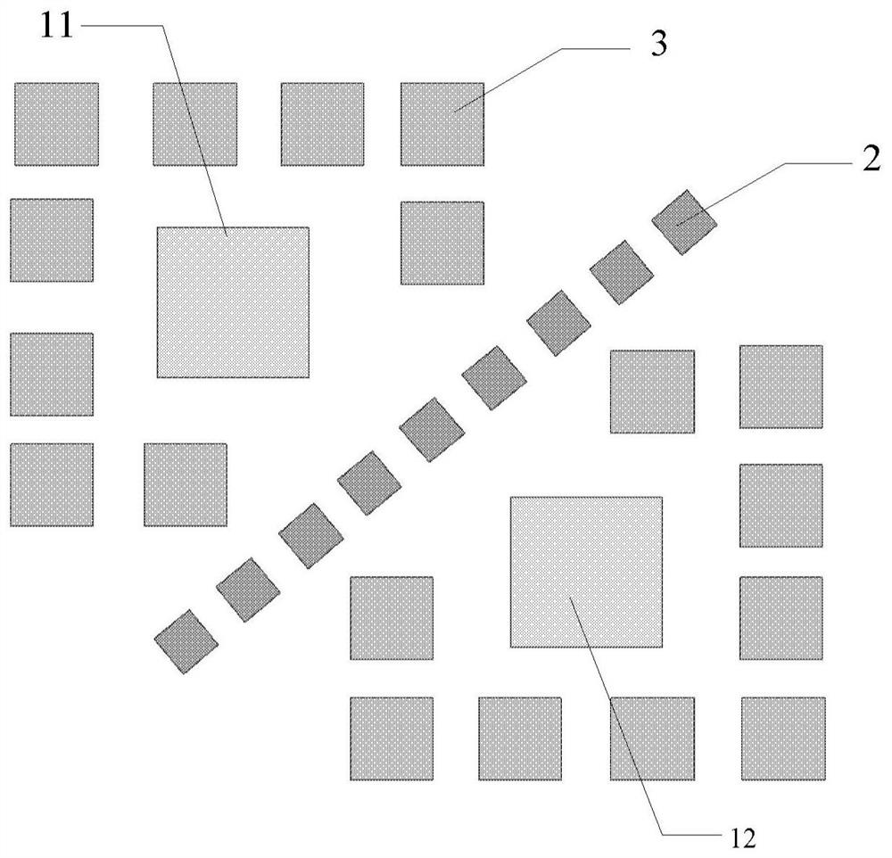
[0006] In order to solve the above-mentioned problems in the prior art, the present disclosure provides a MIMO array antenna beam optimization device and method based on antenna dummy elements, which optimizes the high-density integrated planar array antenna beam. The device is suitable for high-density integrated planar The array antenna can improve the problem of performance degradation caused by the back-connected active circuit and the compact arrangement of the array units. At the same time, it has the advantages of easy processing and low profile. Optimize the electromagnetic boundary of the antenna radiation unit to reduce the distortion of the pattern caused by the asymmetry of the electromagnetic boundary

Method used


Image

  • MIMO array antenna beam optimization device and method based on antenna dummy elements
  • MIMO array antenna beam optimization device and method based on antenna dummy elements
  • MIMO array antenna beam optimization device and method based on antenna dummy elements

Examples


Embodiment Construction

[0024] Hereinafter, embodiments of the present disclosure will be described with reference to the drawings. It should be understood, however, that these descriptions are exemplary only, and are not intended to limit the scope of the present disclosure. In the following detailed description, for purposes of explanation, numerous specific details are set forth in order to provide a thorough understanding of the embodiments of the present disclosure. It may be evident, however, that one or more embodiments may be practiced without these specific details. Also, in the following description, descriptions of well-known structures and techniques are omitted to avoid unnecessarily obscuring the concepts of the present disclosure.

[0025] The terminology used herein is for the purpose of describing particular embodiments only, and is not intended to be limiting of the present disclosure. The terms "comprising", "comprising", etc. used herein indicate the presence of stated features,...


PUM


Abstract

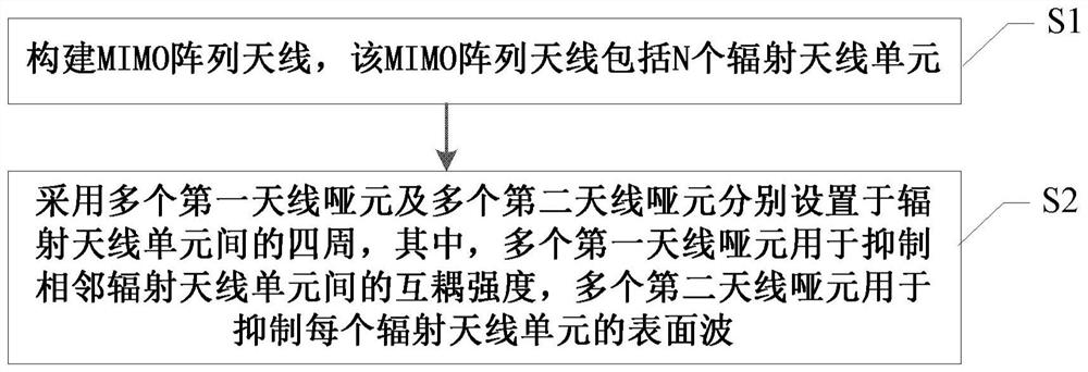
The invention provides an MIMO array antenna beam optimization device based on antenna dummy elements. The device comprises: an MIMO array antenna, which comprises a plurality of radiation antenna units that are used for the radiation or reception of electromagnetic signals; a plurality of first antenna dummy elements which are used for suppressing the mutual coupling strength between the adjacent radiation antenna units; and a plurality of second antenna dummy elements which are used for suppressing the surface wave of each radiation antenna unit. The invention further provides an MIMO array antenna beam optimization method based on the antenna dummy elements.

Description

technical field [0001] The present disclosure relates to the technical field of antennas, and in particular to an antenna dummy-based MIMO array antenna beam optimization device and method. Background technique [0002] MIMO array antennas have been widely used in target detection, data transmission and communication fields due to the characteristics of large number of channels, large spatial freedom, and large channel capacity. With the development of light and small platforms, high-density integrated and miniaturized MIMO array antennas have become an important direction of development. High-density integrated MIMO array antennas often integrate antennas and radio frequency channels to greatly reduce size, volume, etc. , but the high integration level leads to serious coupling between MIMO antenna units and sub-arrays, the beam distortion of the pattern, the further deterioration of the antenna pattern distortion caused by active devices, and the narrowing of the bandwidth...

Claims


Application Information

Patent Timeline
IPC IPC(8): H01Q21/00H01Q1/36
CPCH01Q21/00H01Q1/36H01Q1/523H01Q21/065H01Q21/28
Inventor 王雪梅丁满来唐跞丁赤飚曲佳萌吴蒙
Owner AEROSPACE INFORMATION RES INST CAS
Learn More