

Slender hole machining device and method
A processing device and a technology of elongated holes, which are applied in the direction of driving devices, feeding devices, metal processing equipment, etc., can solve the problems of unsuitable drilling of elongated holes on the outer wall of the hull, and reduce risks, improve stability, and improve safety Effect
- Summary
- Abstract
- Description
- Claims
- Application Information
AI Technical Summary
Problems solved by technology
Method used
Image

Examples
specific Embodiment approach 1
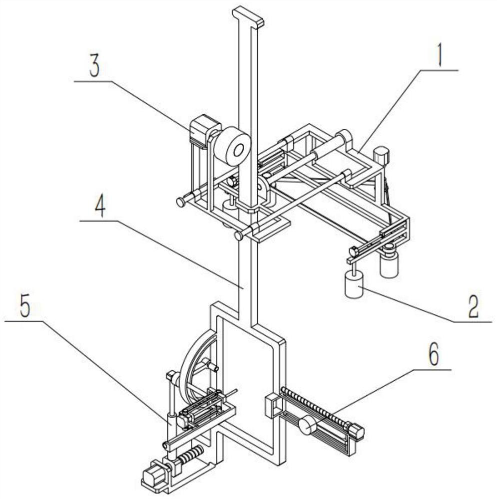
[0037] Such as Figure 1-9 As shown, a slender hole processing device includes a power frame 1, a clamping mechanism 2, a moving mechanism 3, a lifting mechanism 4, a hole processing mechanism 5 and a marking mechanism 6, and the left and right ends of the rear end of the power frame 1 are respectively provided with a The clamping mechanism 2 and the moving mechanism 3 are connected to the middle of the upper end of the power frame 1, the lifting mechanism 4 is slidably connected to the moving mechanism 3, the hole processing mechanism 5 is connected to the left end of the lower end of the lifting mechanism 4, and the marking mechanism 6 is connected to the lower end of the lifting mechanism 4 the right end of .
[0038] The present invention can process the elongated holes on the outer wall of the hull, which is convenient for the hull to fix the pendant on the outer wall of the hull. Clamping and moving under the action of the power frame 1, it is convenient to manually con...
specific Embodiment approach 2
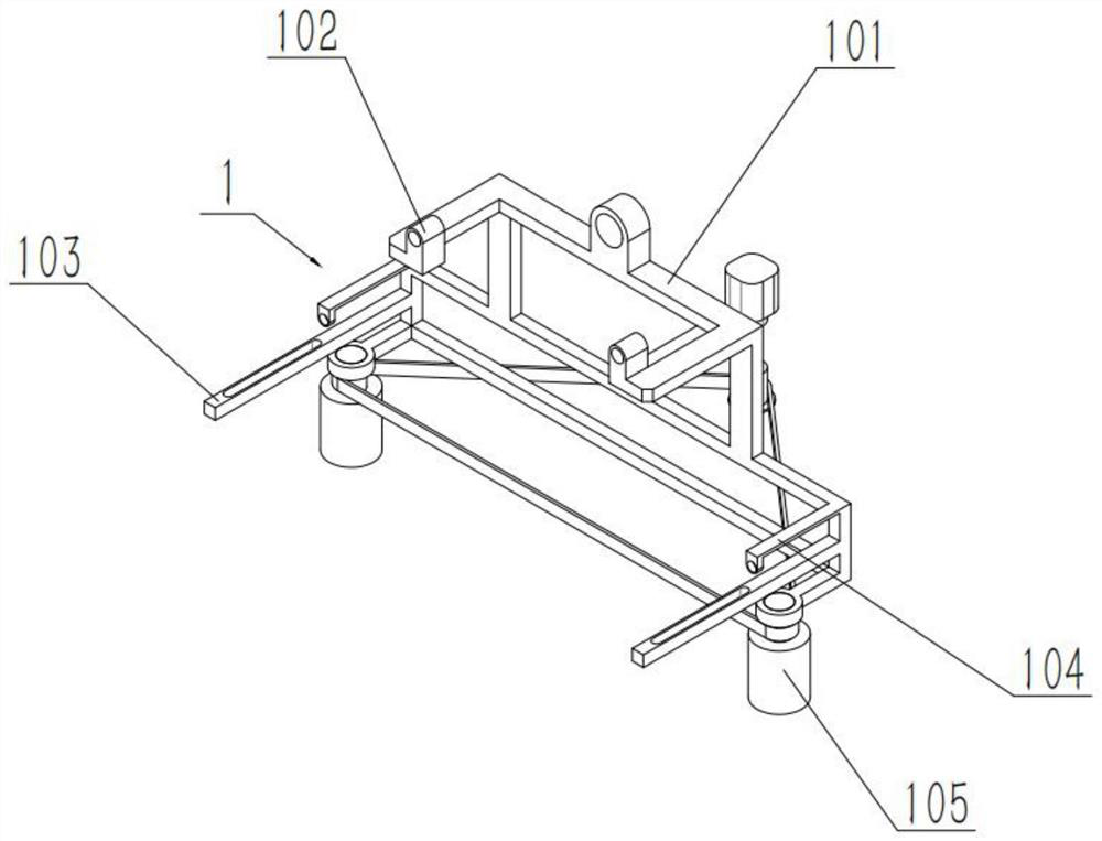
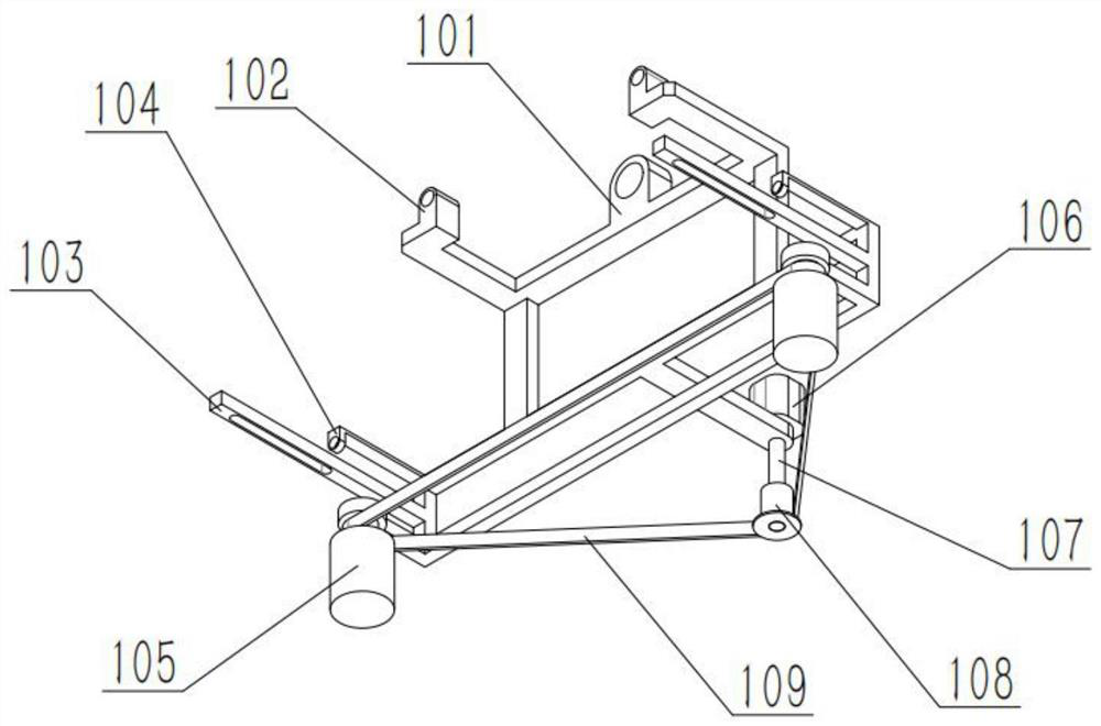
[0040] Such as Figure 1-9As shown, a kind of slender hole machining device, power frame 1 comprises frame body 101, convex seat 102, strip orifice plate 103, right-angle plate 104, turning wheel 105, motor I 106, turning bar 107, power wheel 108 and belt 109, The left and right ends of the upper rear end of the frame body 101 are respectively provided with a convex seat 102, the left and right ends of the lower rear end of the frame body 101 are respectively provided with a strip orifice 103, and the left and right ends of the lower rear end of the frame body 101 are respectively provided with A right-angle plate 104, the left and right ends of the lower end of the frame body 101 are respectively rotatably connected to a rotating wheel 105, the output shaft of the motor I 106 is fixedly connected to the rotating rod 107 through a coupling, the power wheel 108 is fixedly connected to the lower end of the rotating rod 107, and the motor I106 is fixedly connected to the middle p...
specific Embodiment approach 3
[0042] Such as Figure 1-9 As shown, a slender hole processing device, the clamping mechanism 2 includes an electric push rod I201, a moving block 202, a pole 203 and a clamping wheel 204, the moving block 202 is fixedly connected to the movable end of the electric push rod I201, and the pole 203 is fixedly connected to the lower end of the moving block 202, and the clamping wheel 204 is connected to the lower end of the pole 203 in rotation. Above, the two struts 203 are slidingly connected to the two strip orifice plates 103 respectively. Clamping the outer wall of the hull is convenient to drive two electric push rods I 201 to drive two clamping wheels 204 close to the two rotating wheels 105 before drilling the outer wall of the hull, so that the outer wall of the hull can be clamped, and the two clamping wheels The surface of 204 is relatively rough.
PUM
 Abstract
Description
Claims
Application Information