Automatic key pulling device for plate cylinder plugs

A plug-and-roll technology, which is applied to broaching device, accessories of broaching device, broaching machine, etc., can solve the problems of unsatisfactory production efficiency, manual installation of plugs, low automation level, etc., and achieve seamless The effect of docking, improving the level of automation, and high degree of automation

Pending Publication Date: 2021-06-29
SHANGHAI YUNCHENG PLATE MAKING
View PDF1 Cites 0 Cited by
  • Summary
  • Abstract
  • Description
  • Claims
  • Application Information

AI Technical Summary

Problems solved by technology

Although the pull key device in this patent can process multiple plug pieces at one time, each plug piece needs to be manually installed, and cannot be connected with the plug automatic production line. The automation level is low, and the production efficiency cannot meet the requirements of the current automation factory needs

Method used


Image

  • Automatic key pulling device for plate cylinder plugs
  • Automatic key pulling device for plate cylinder plugs

Examples


Embodiment 1

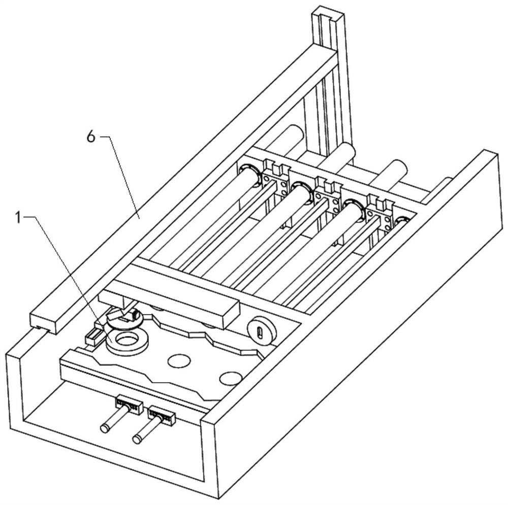
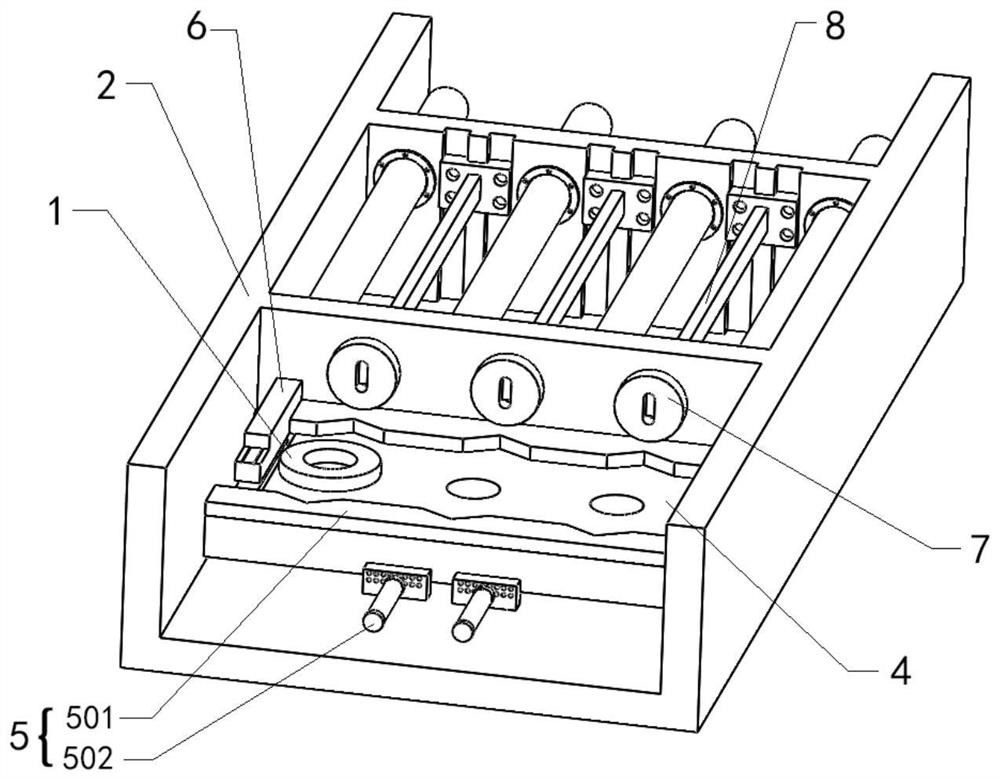
[0027] An automatic key pulling device for plate roller plugs, which is used to perform key pulling operations on plate roll plugs 1, and its structure is as follows figure 1 with figure 2 As shown, the automatic key pulling device includes a frame platform 2, a plug loading and unloading mechanism 3, a plug placing frame 4, a plug positioning mechanism 5, a rotary pressing mechanism 6, a grinding tool 7, a key pulling tool rail 8 and a key pulling mechanism. Tool rail drive mechanism. The plug loading and unloading mechanism 3 is installed on the top of the frame platform 2, the plug placement frame 4, the plug positioning mechanism 5, the rotating and pressing mechanism 6, the grinding tool 7, the pull key knife rail 8 and the key pull knife rail driving mechanism respectively Installed on the frame platform 2, the plug positioning mechanism 5 is installed on the plug placement frame 4, the output shaft of the rotary pressing mechanism 6 is connected with the plug placemen...

Embodiment 2

[0044] An automatic key pulling device for plate roller plugs, which is used to perform key pulling operations on plate roll plugs 1, and its structure is as follows figure 1 with figure 2 As shown, the automatic key pulling device includes a frame platform 2, a plug loading and unloading mechanism 3, a plug placing frame 4, a plug positioning mechanism 5, a rotary pressing mechanism 6, a grinding tool 7, a key pulling tool rail 8 and a key pulling mechanism. Tool rail drive mechanism. The plug loading and unloading mechanism 3 is installed on the top of the frame platform 2, the plug placement frame 4, the plug positioning mechanism 5, the rotating and pressing mechanism 6, the grinding tool 7, the pull key knife rail 8 and the key pull knife rail driving mechanism respectively Installed on the frame platform 2, the plug positioning mechanism 5 is installed on the plug placement frame 4, the output shaft of the rotary pressing mechanism 6 is connected with the plug placemen...


PUM


Abstract

The invention relates to an automatic key pulling device for plate cylinder plugs. The automatic key pulling device is used for carrying out key pulling operation on the plate cylinder plugs and comprises a rack platform, a plug feeding and discharging mechanism, a plug placing frame, a plug positioning mechanism, a rotary pressing mechanism, a grinding tool, a key pulling tool path and a key pulling tool path driving mechanism, wherein the plug feeding and discharging mechanism is installed at the top of the rack platform, the plug placing frame, the plug positioning mechanism, the rotary pressing mechanism, the grinding tool, the key pulling tool path and the key pulling tool path driving mechanism are installed on the rack platform, the plug positioning mechanism is installed on the plug placing frame, an output shaft of the rotary pressing mechanism is connected with the plug placing frame, the grinding tool is fixed on the rack platform, the grinding tool is provided with an inserting hole for the key pulling tool path to penetrate through, one end of the key pulling tool path penetrates through the inserting hole in the grinding tool, and the other end of the key pulling tool path is connected with the key pulling tool path driving mechanism. Compared with the prior art, and the automatic key pulling device has the advantages of high automation degree, wide application range, high key pulling precision and the like.

Description

technical field [0001] The invention relates to the technical field of plate roll processing, in particular to an automatic key pulling device for plate roll plugging. Background technique [0002] At present, although the keyway processing of the plate roller plug is automatically processed, its loading and unloading system is still manual, so the automatic production line cannot be incorporated into the automatic line in terms of the keyway processing's loading and unloading. [0003] As disclosed in Chinese patent CN209006779U, a plate roller plugging and pulling key device is disclosed, which includes a frame platform, and the frame platform is provided with a pulling key fixing plate and a plug fixing plate, and the pulling key fixing plate and the plugging The head fixing plates are fixedly connected by connecting rods, and the surface of the side of the plug fixing plate is integrally formed with a cylindrical boss, and the cylindrical boss is provided with a plug for...

Claims


Application Information

Patent Timeline
Patent Type & Authority Applications(China)
IPC IPC(8): B23D41/06B23D39/00B23D37/22
CPCB23D37/22B23D39/00B23D41/06
Inventor 盖胜强王晓飞张俊礼
Owner SHANGHAI YUNCHENG PLATE MAKING
Why Eureka
Try Eureka