Eureka AIR delivers breakthrough ideas for toughest innovation challenges, trusted by R&D personnel around the world.

Tin dispensing device for PCB in building automation equipment

A technology for building automation and PCB boards, applied in auxiliary devices, welding equipment, metal processing equipment, etc., can solve the problems that PCB boards cannot play their essential role, cannot fully guarantee operators, and affect users' use, so as to avoid leakage points Phenomenon, reduce labor intensity, improve the effect of precision

Inactive Publication Date: 2021-06-29
重庆振多弱电工程有限公司
View PDF9 Cites 1 Cited by
  • Summary
  • Abstract
  • Description
  • Claims
  • Application Information

AI Technical Summary

Problems solved by technology

[0002] The PCB board is an important electronic component and a support for electronic components. At present, the PCB boards on the market are tinned, and some of them are tinned by hand. The production method of this PCB board is relatively simple, and it is easy to cause excessive tin on the PCB. Or too little, causing the PCB board to fail to play its essential role, such as the patent with the publication number CN211531456U, although it has realized automatic tinning, and to a certain extent, it has avoided the human body's inhalation of harmful gases and contact with high-temperature devices during the tinning process. touch, but in the process of placing and picking up the PCB board, it cannot completely guarantee that the operator will not be harmed, and the long-term emission of harmful gases will have an impact on the surrounding environment, and the equipment that uses tin wire to touch tin, It is necessary to stop the equipment to load the tin wire, and the process of replacing the tin wire is also relatively cumbersome, which affects the use of users

Method used


Image

  • Tin dispensing device for PCB in building automation equipment
  • Tin dispensing device for PCB in building automation equipment
  • Tin dispensing device for PCB in building automation equipment

Examples


Embodiment Construction

[0025] The following will clearly and completely describe the technical solutions in the embodiments of the present invention with reference to the accompanying drawings in the embodiments of the present invention. Obviously, the described embodiments are only some, not all, embodiments of the present invention. Based on the embodiments of the present invention, all other embodiments obtained by persons of ordinary skill in the art without making creative efforts belong to the protection scope of the present invention.

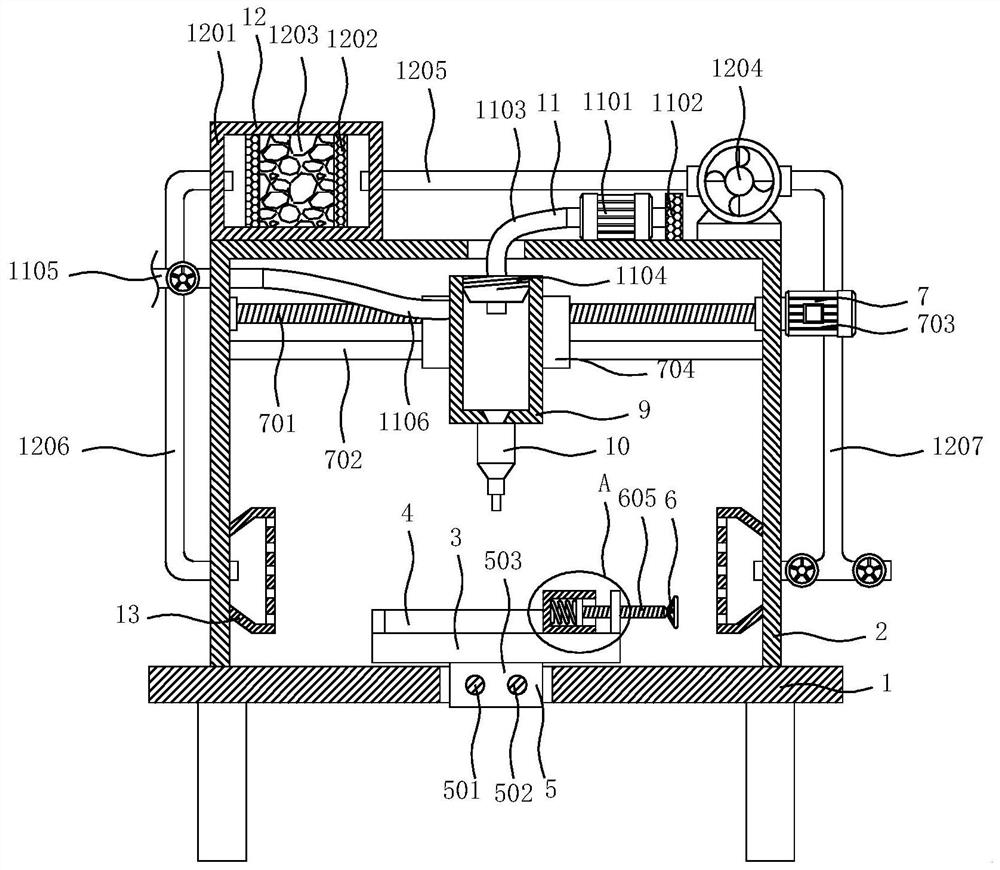
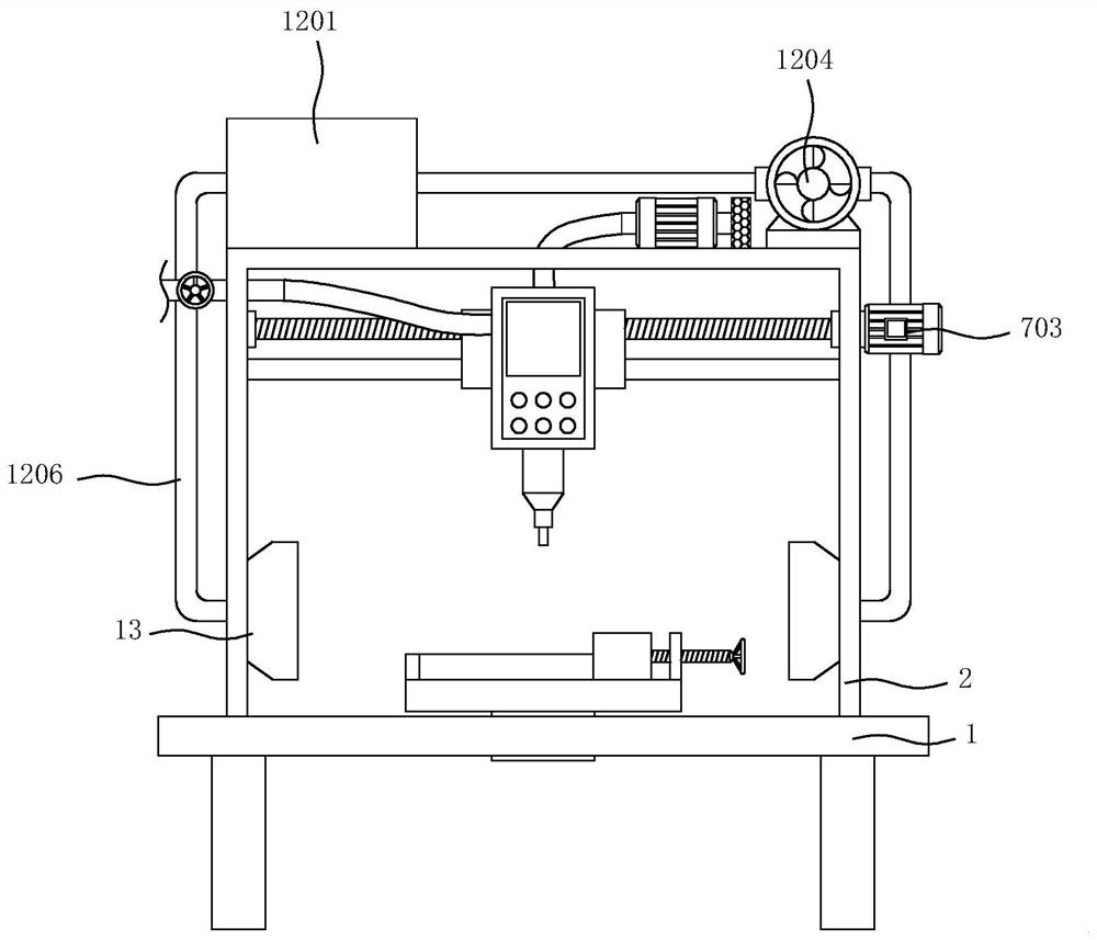
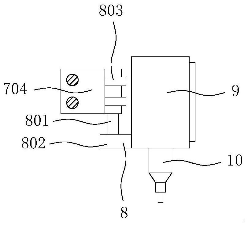
[0026] see Figure 1-7 , the present invention provides a technical solution: a tin spotting device for PCB boards in building automation equipment, including a workbench 1, a frame 2 is fixedly installed on the top of the workbench 1, an opening is opened on the top of the frame 2, and the workbench 1 is provided with a solid material table 3, the top of the solid material table 3 is fixedly installed with a positioning rectangular plate 4, the bottom of the ...


PUM


Abstract

The invention discloses a tin dispensing device for a PCB in building automation equipment, and relates to the technical field of PCB production. The tin dispensing device for the PCB in the building automation equipment comprises a workbench, a frame is fixedly installed at the top of the workbench, an opening is formed in the top of the frame, a material fixing table is arranged above the workbench, a positioning right-angle plate is fixedly installed at the top of the material fixing table, a moving mechanism is arranged at the bottom of the material fixing table, a clamping mechanism is arranged at the top of the material fixing table, and moving mechanisms are arranged on the inner walls of the two sides of the frame. According to the tin dispensing device for the PCB in the building automation equipment, tin dispensing is conducted in a tin paste dispensing mode, through cooperative use of a pressure pump, a filter screen, a hose, a threaded plug, a feeding pipe and a feeding hose, in the using process of the device, the device does not need to be stopped, the tin paste can be added to the device, a user can use the device conveniently, and the popularization of the device is further improved.

Description

technical field [0001] The invention relates to the technical field of PCB board production, in particular to a tin spotting device for PCB boards in building automation equipment. Background technique [0002] The PCB board is an important electronic component and a support for electronic components. At present, the PCB boards on the market are tinned, and some of them are tinned by hand. The production method of this PCB board is relatively simple, and it is easy to cause excessive tin on the PCB. Or too little, causing the PCB board to fail to play its essential role, such as the patent with the publication number CN211531456U, although it has realized automatic tinning, and to a certain extent, it has avoided the human body's inhalation of harmful gases and contact with high-temperature devices during the tinning process. touch, but in the process of placing and picking up the PCB board, it cannot completely guarantee that the operator will not be harmed, and the long-te...

Claims


Application Information

Patent Timeline
IPC IPC(8): B23K3/00B23K3/08
CPCB23K3/00B23K3/08
Inventor 周祥林
Owner 重庆振多弱电工程有限公司
Why Eureka
Eureka Blog
Learn More