Rapid laser material packaging device for intelligent manufacturing

A laser material and packaging device technology, which is applied in the field of laser material rapid packaging devices for intelligent manufacturing, can solve the problems of cumbersome and labor-intensive replacement of laser materials

Inactive Publication Date: 2021-06-29
王华
View PDF0 Cites 2 Cited by
  • Summary
  • Abstract
  • Description
  • Claims
  • Application Information

AI Technical Summary

Problems solved by technology

[0004] In order to overcome the shortcomings that it takes a lot of effort for workers to manually cover the semiconductor film packaging, and the process of replacing laser materials is cumbersome for workers, and when workers cover the film, the laser materials will move freely and affect the film coating effect. The purpose of the present invention is to provide a A rapid packaging device for laser materials for intelligent manufacturing that can cover and package laser materials, replace laser materials at intervals, complete control of laser materials, and position laser materials to avoid movement

Method used


Image

  • Rapid laser material packaging device for intelligent manufacturing
  • Rapid laser material packaging device for intelligent manufacturing
  • Rapid laser material packaging device for intelligent manufacturing

Examples


Embodiment 1

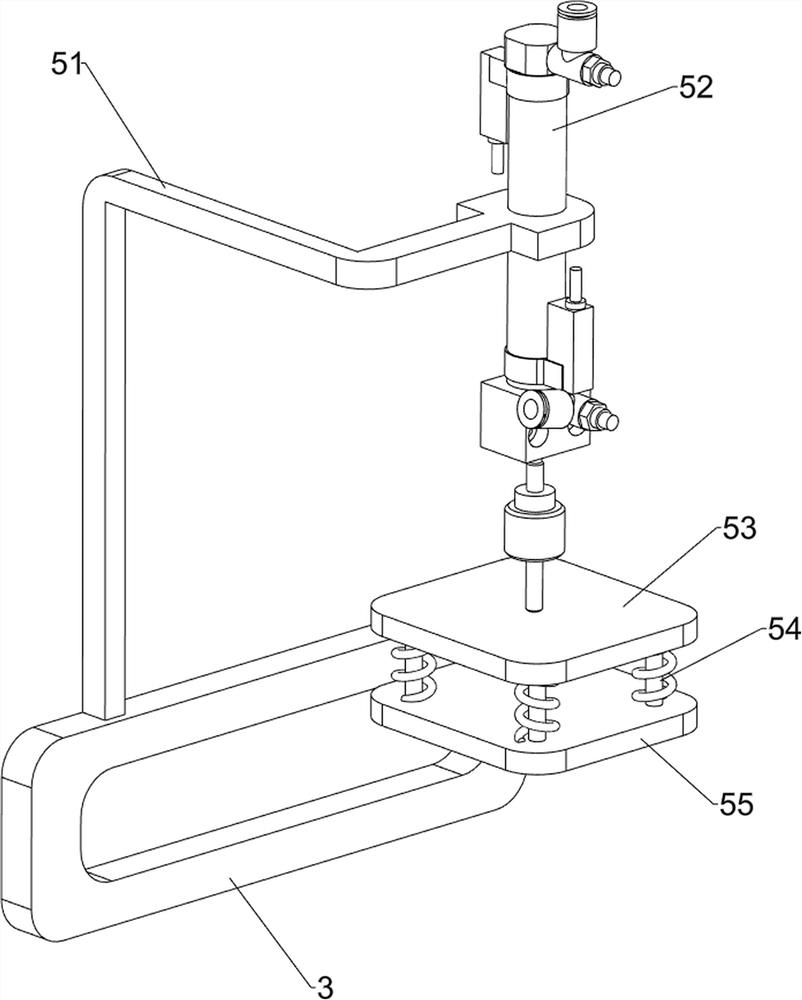
[0072] A laser material rapid packaging device for intelligent manufacturing, such as figure 1 and figure 2As shown, it includes a base 1, a support frame 2, a first fixed frame 3, a film winding mechanism 4 and a packaging mechanism 5. The support frame 2 is symmetrically arranged on the left and right sides of the top of the base 1, and the front and rear sides of the support frame 2 are welded with the first A fixed frame 3, a film winding mechanism 4 is installed between the two first fixed frames 3, and a packaging mechanism 5 is provided on the left side of the first fixed frame 3 on the rear side, and the packaging mechanism 5 is in contact with the film winding mechanism 4.

[0073] When a worker needs to cover and package the laser material, the worker first needs to wind the semiconductor film 46 on the film winding mechanism 4, and then the worker needs to manually move the laser material to the bottom of the film winding mechanism 4. When the laser material is loc...

Embodiment 2

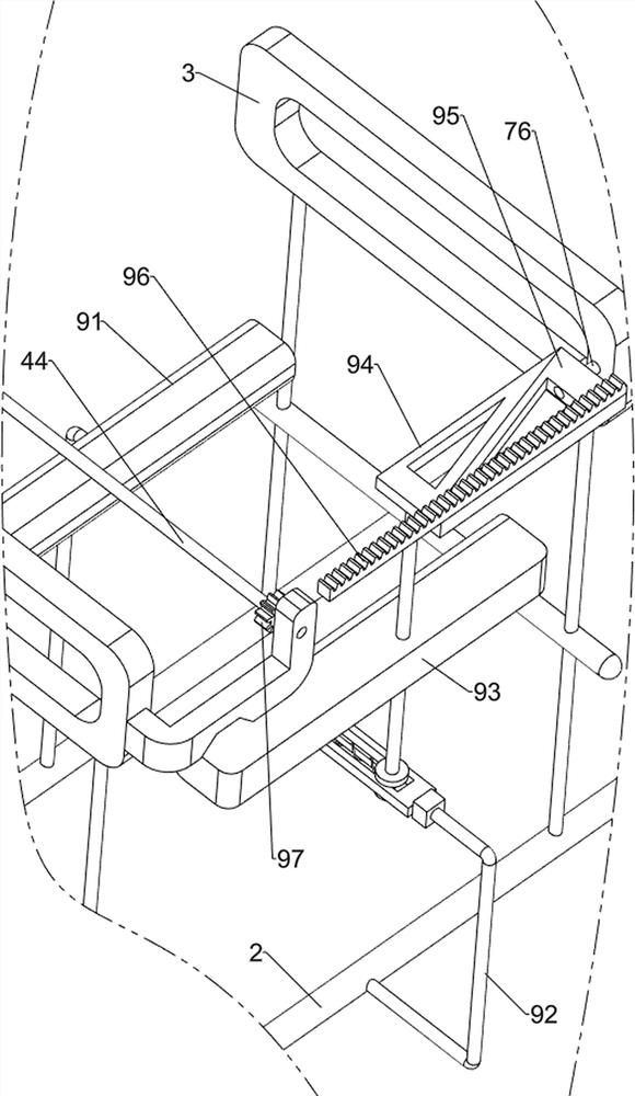
[0075] In a preferred embodiment of the present invention, as image 3 As shown, the film winding mechanism 4 includes a first bearing seat 41, a first rotating shaft 42, a second bearing seat 43, a second rotating shaft 44, a film winding wheel 45 and a semiconductor film 46, and the front side of the first fixed mount 3 on the rear side Two first bearing blocks 41 are fixedly connected to the upper part, and a first rotating shaft 42 is arranged between the first bearing blocks 41. Two second bearing blocks 43 are fixedly connected to the upper part of the rear side of the first fixed frame 3 on the front side. A second rotating shaft 44 is arranged between the bearing blocks 43 , a film winding wheel 45 is fixedly connected to the first rotating shaft 42 , and a semiconductor thin film 46 is wound on the film winding wheel 45 .

[0076] Workers first need to wind the semiconductor film 46 on the film winding wheel 45 and the second rotating shaft 44, the film winding wheel ...

Embodiment 3

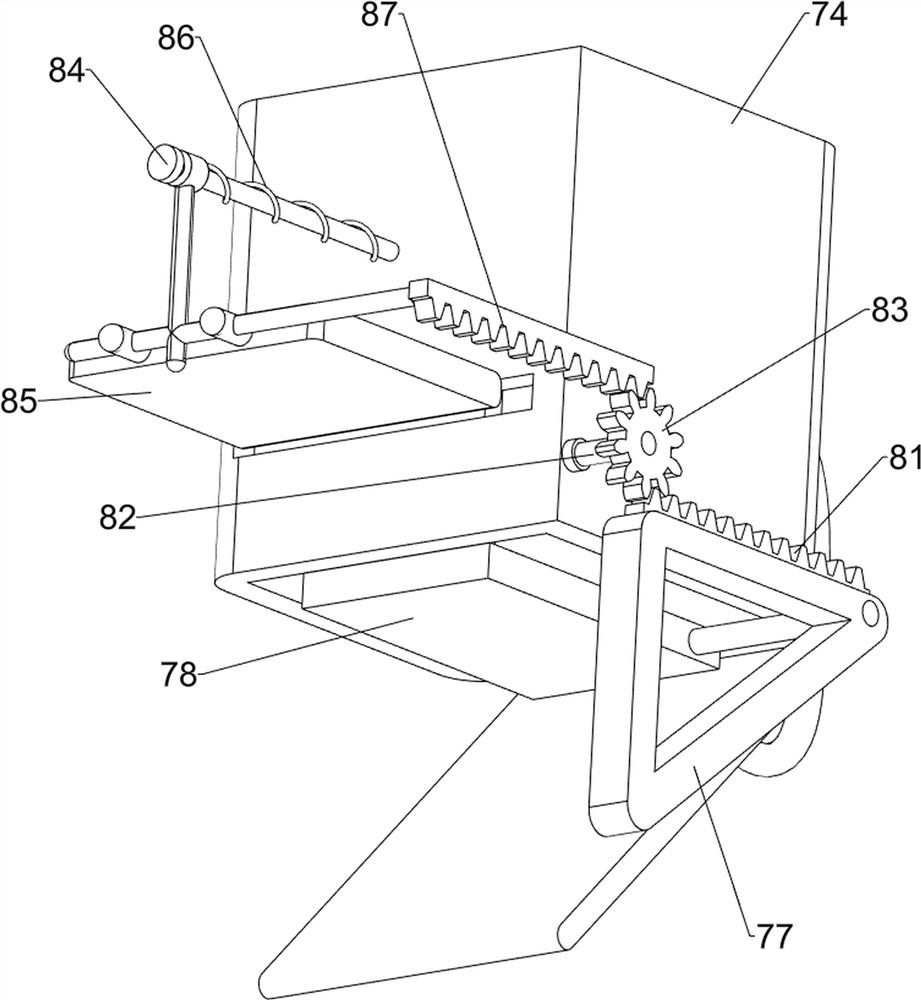
[0078] In a preferred embodiment of the present invention, as figure 1 , figure 2 , Figure 4 , Figure 5 , Image 6 , Figure 7 , Figure 7 and Figure 8 As shown, the packaging mechanism 5 includes a second fixed frame 51, a cylinder 52, a fixed plate 53, a telescopic assembly 54 and a heat-press assembly 55, and the second fixed frame 51 is welded on the left side of the top of the first fixed frame 3 on the rear side. The upper part of the fixed frame 51 is fixedly connected with a cylinder 52 by bolts, and the bottom end of the telescopic rod of the cylinder 52 is fixedly connected with a fixed plate 53, and the left and right sides of the bottom of the fixed plate 53 are symmetrically provided with telescopic assemblies 54, and the bottoms of the four telescopic assemblies 54 are connected. There is a thermocompression assembly 55 .

[0079] When the laser material is located under the semiconductor film 46, the worker needs to start the expansion and contraction...


PUM


Abstract

The invention relates to a packaging device, in particular to a rapid laser material packaging device for intelligent manufacturing. The invention provides a rapid laser material packaging device for intelligent manufacturing, capable of covering a laser material with a film for packaging, replacing the laser material at intervals, finishing material control work of the laser material, and positioning the laser material to avoid movement. The packaging device, in particular to a rapid laser material packaging device for intelligent manufacturing comprises a base, a supporting frame and a first fixed frame, wherein the supporting frame is symmetrically arranged on the two sides of the top of the base, and the first fixed frame is welded to the two sides of the supporting frame. For the rapid laser material packaging device for intelligent manufacturing, by arranging a film winding mechanism to be matched with a packaging mechanism, packaging work of the laser material can be realized; a moving mechanism is matched with the supporting frame, and conveying work of the laser material can be achieved; a discharging mechanism is matched with the material control mechanism, and interval material control work of the laser material can be achieved; and the positioning mechanism is matched with the discharging mechanism, so that clamping work of the laser material can be realized.

Description

technical field [0001] The invention relates to a packaging device, in particular to a laser material rapid packaging device for intelligent manufacturing. Background technique [0002] Laser materials are mainly condensed matter, mainly solid laser materials. Solid laser materials are divided into two types: crystal and amorphous glass. Crystal is a semiconductor laser material mainly driven by electricity. It generally adopts a heterogeneous structure and is composed of semiconductor thin films. , made by epitaxial method and vapor deposition method. Amorphous glass is a luminescent material that absorbs optical pump energy through discrete luminescent centers and converts it into laser output. This type of material is based on a solid dielectric, and it takes a lot of work for workers to manually cover the semiconductor film. At the same time, the process for workers to replace the laser material is cumbersome, and when workers cover the film, the laser material will move...

Claims


Application Information

Patent Timeline
Patent Type & Authority Applications(China)
IPC IPC(8): B29C63/02B29C63/00B29C65/02B29C65/78
CPCB29C63/0004B29C63/02B29C65/02B29C65/7805B29C65/7841
Inventor 王华
Owner 王华
Why Eureka
Try Eureka