Water immersion control circuit for medical instrument
A technology for controlling circuits and medical instruments, applied in the medical field, can solve problems such as flow into the hospital, damage to medical instruments, etc., and achieve the effect of easy viewing and faster drainage
- Summary
- Abstract
- Description
- Claims
- Application Information
AI Technical Summary
Problems solved by technology
Method used
Image

Examples
Embodiment 1
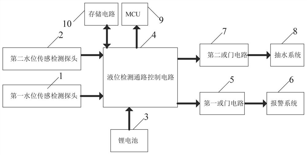
[0023] A medical instrument water immersion control circuit, such as figure 1 As shown, it includes a first water level sensor detection probe 1, a second water level sensor detection probe 2, a lithium battery 3, a liquid level detection channel control circuit 4, a first OR gate circuit 5, an alarm system 6, and a second OR gate circuit 7 and the pumping system 8, the first water level sensor detection probe 1 and the second water level sensor detection probe 2 are connected to the input end of the liquid level detection path control circuit 4, and the output end of the liquid level detection path control circuit 4 is connected to the first water level detection path control circuit 4. The input end of an OR gate circuit 5 is connected, the output end of the first OR gate circuit 5 is connected to the alarm system 6, the output end of the liquid level detection path control circuit 4 is connected to the input end of the second OR gate circuit 7 , the output end of the second...
Embodiment 2
[0026] On the basis of Example 1, such as figure 1 As shown, it also includes an MCU9, which is connected to the output end of the liquid level detection channel control circuit 4, and the lithium battery 3 supplies power to the MCU9.
[0027] When any one of the first water level sensor detection probe 1 and the second water level sensor detection probe 2 detects that the water level is too high, the MCU9 controls the relevant equipment to work, drain water, and speed up the drainage. The first water level sensor detects probe 1 and the second water level. When any one of the sensor detection probes 2 detects that the water level does not exceed the warning line, the CU controls related equipment to shut down.
[0028] It also includes a storage circuit 10 , the input end of the storage circuit 10 is connected to the output end of the liquid level detection path control circuit 4 , and the lithium battery 3 is the storage circuit 10 .
[0029] The first water level sensor de...
Embodiment 3
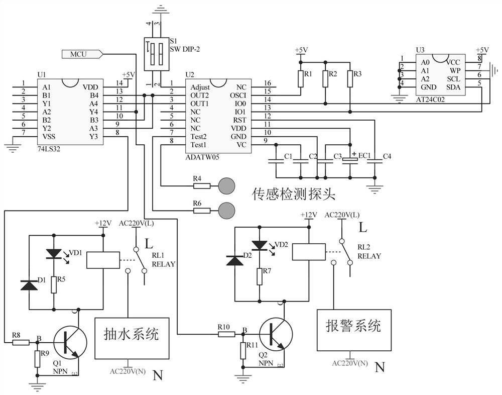
[0031] A medical instrument water immersion control circuit, such as figure 2As shown, the liquid level detection path control circuit 4 includes a liquid level detection integrated circuit ASATW05-U2, a dial switch S1, a resistor R1, a resistor R2, a resistor R3, a resistor R4, a resistor R5, an electrolytic capacitor EC1, a capacitor C1, Capacitor C2, capacitor C3 and capacitor C4, pin 1 of the liquid level detection integrated circuit ASATW05-U2 is connected to pin 2 of the dial switch S1, pin 3 of the dial switch S1 is grounded, and the liquid level detection integrated circuit Pin 7 of ASATW05-U2 is connected to one end of resistor R6, the other end of resistor R6 is connected to the detection probe 2 of the second water level sensor, pin 8 of the liquid level detection integrated circuit ASATW05-U2 is connected to one end of resistor R4, The other end of the resistor R4 is connected to the first water level sensor detection probe 1, the 9-pin series capacitor C1 of the ...
PUM
 Abstract
Description
Claims
Application Information
 - Generate Ideas
- Intellectual Property
- Life Sciences
- Materials
- Tech Scout
- Unparalleled Data Quality
- Higher Quality Content
- 60% Fewer Hallucinations
Browse by: Latest US Patents, China's latest patents, Technical Efficacy Thesaurus, Application Domain, Technology Topic, Popular Technical Reports.
© 2025 PatSnap. All rights reserved.Legal|Privacy policy|Modern Slavery Act Transparency Statement|Sitemap|About US| Contact US: help@patsnap.com