Intelligent electric power cabinet

A technology of intelligent power and power cabinets, which is applied in the direction of electrical components, panel/switch station circuit devices, substation/distribution device shells, etc., which can solve the problem of affecting the normal use and safety of power devices, and the unsatisfactory heat dissipation and dehumidification effects of power cabinets , Intelligent control of temperature and humidity and other issues, to achieve the effect of convenient maintenance and replacement, improved moisture-proof and cooling capabilities, and simple installation methods

Active Publication Date: 2021-06-29
天津嘉能电力技术有限公司
View PDF14 Cites 2 Cited by
  • Summary
  • Abstract
  • Description
  • Claims
  • Application Information

AI Technical Summary

Problems solved by technology

[0002] Power cabinets are often used to place power devices that work continuously. These power devices often generate a lot of heat when they work. If the heat cannot be dissipated in time, it will affect the normal use and even the safety of the power devices.
[0003] The existing power cabinet generally has a built-in fan, and the external cold air is introduced into the power cabinet through the fan to dissipate heat from the power devices. However, the fans in the existing power cabinet are often installed directly in the power cabinet, and there is no Excessive heat and long-term operation of the fan will cause waste of power resources, and most of the existing power cabinets do not have intelligent control of temperature and humidity equipment, resulting in very unsatisfactory heat dissipation and dehumidification effects in the power cabinet. Reduced service life of the power cabinet

Method used


Image

  • Intelligent electric power cabinet
  • Intelligent electric power cabinet
  • Intelligent electric power cabinet

Examples


Embodiment 1

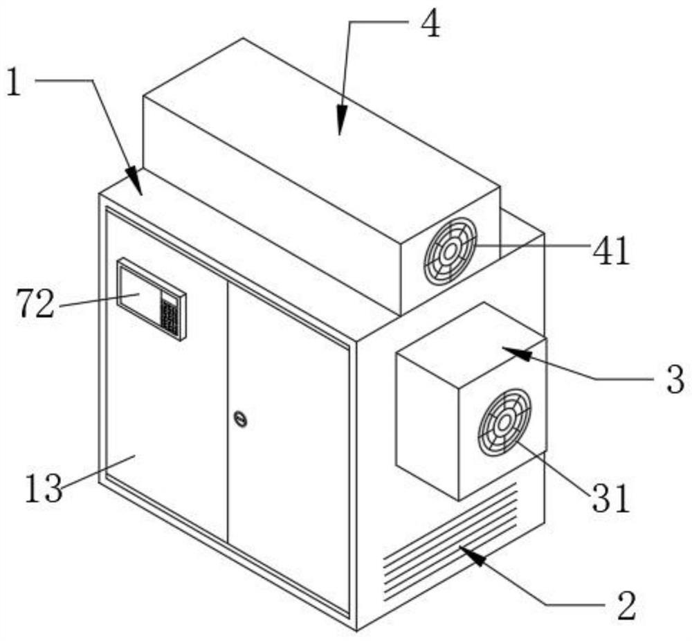
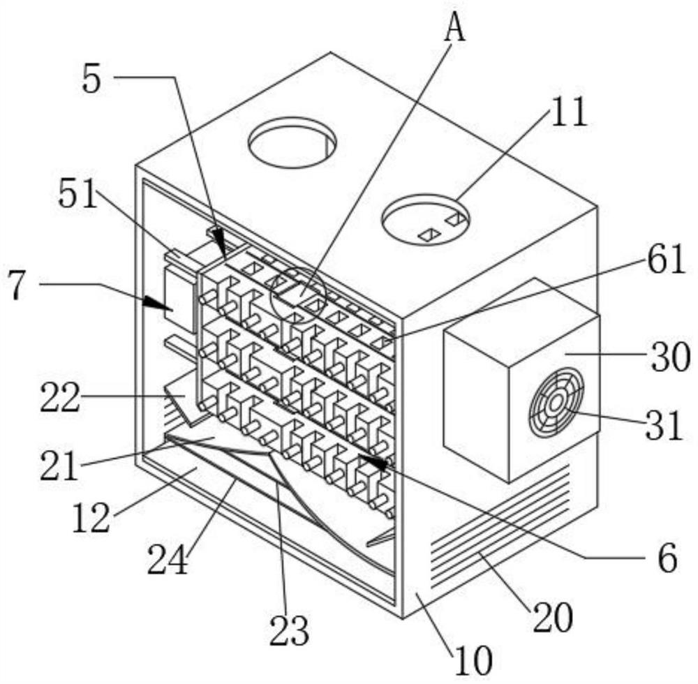
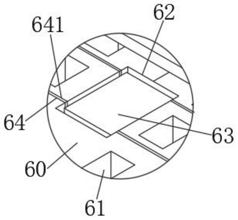
[0048] Intelligent power cabinet, such as Figure 1 - Figure 2 As shown, including: body structure 1, heat sink mechanism 2, support mechanism 5, electrical component mechanism 6, and control mechanism 7;

[0049] Among them, if Figure 1-2 As shown, the main body structure 1 includes a power cabinet body 10, a first round hole 11, a storage product 12, a cabinet door 13, and a side hole 17, and a first round hole 11, a power cabinet body 10 is opened. A side hole 17 is opened on the side.

[0050] Among them, if figure 2 as well as Figure 6 - Figure 7 As shown, the heat radiating mechanism 2 includes a strip vent 20 and an arcuate air strip 21 and a straight plate 22, and a strip vent 20 is disposed on both sides of the bottom of the power cabinet body 10, and the opposite surface of the two strip vent 20. The upper attachment of the arcuate guide plate 21 and the straight plate 22 are fixed, and the fixed connection of the two arcuate air strip 21 is attached.

[0051] Among them,...

Embodiment 2

[0055] Such as Figure 1 - Figure 2 as well as Figure 7 As shown, the present embodiment differs from the first embodiment in that the smart power cabinet includes a refrigeration mechanism 3, and the refrigeration mechanism 3 includes a first chassis 30, a first heat sink 31, a refrigerator 32, and a cold wind port 33, A chassis 30 is fixedly mounted on one side of the power cabinet body 10, and the first chassis 30 is disposed on one side of the power cabinet body 10, and the first heat sink 31 is fixed, and the first chassis 30 is fixedly mounted. 32, the refrigerator One side of 32 is provided with a cold spray port 33, and one end of the cold air port 33 is penetrated at the side hole 17.

[0056] By adopting the above technical solution, the smart power cabinet also has a refrigeration mechanism 3, and the refrigeration mechanism 3 is composed of a first chassis 30, a first heat sink 31, a refrigerator 32, and a cold air port 33. When used, in the main body structure 1 When t...

Embodiment 3

[0058] Such as figure 1 , Figure 7 as well as Figure 9 As shown, the present embodiment differs from the second embodiment in that the smart power cabinet, further includes a drying mechanism 4, a drying mechanism 4 including a second chassis 40, a second heat sink 41, and a hot blower 42, second The chassis 40 is fixedly mounted on the top of the power cabinet body 10, and a second heat sink 41 is provided on one side of the second chassis 40, and a hot blower 42 is provided in the second chassis 40.

[0059] By using the above technical solution, the smart power cabinet also has a drying mechanism 4, and the drying mechanism 4 consists of a second chassis 40, a second heat sink 41, and a hot blower 42. When used, when the main body structure 1 is tidy When the heat gas generated by the heat blower 42, the electrical component mechanism 6 in which the main body structure 1 is blown into the main body structure 1 is blown into the main body structure 1 through the first round hole...


PUM


Abstract

The invention discloses an intelligent electric power cabinet which comprises a main body structure, a heat dissipation mechanism, a support mechanism, an electrical component mechanism and a control mechanism. The main body structure comprises an electric power cabinet body, a first round hole, a storage grid, a cabinet door and a side hole. According to the invention, the interior of the main body structure can be rapidly cooled through a refrigerator, moisture in the main body structure can be rapidly dried through a hot air blower, the humidity and the temperature on the electrical component strip can be detected in a large area by connecting a humidity sensing line and a temperature sensing line to the detector so that the detection data is more accurate, and the control mechanism is connected with the detector through a wire; and data detected by the detector can be transmitted to the control mechanism so that the inspection work of a worker is facilitated, the waste of electric power resources during long-term work of the refrigeration mechanism is avoided, and the temperature and humidity conditions in the main body structure can be intelligently mastered and controlled.

Description

Technical field [0001] The present invention relates to the field of electric cabinets, and more particularly, it involves a smart power cabinet. Background technique [0002] Power cabinets are often used to place continuously working power devices, which often produce a large amount of heat when working, if heat is not available in time, will affect the normal use of power devices and even use safety. [0003] In the existing power cabinet, there is generally built-in fan, and the externally cold wind is introduced into the power cabinet in the power cabinet, but the fan in the existing power cabinet is often mounted in the power cabinet, not in the power cabinet. Excessive heat, as well as the fan for a long time, which causes waste of power resources, and the existing equipment without intelligence is unable to master the temperature and humidity, resulting in the heat dissipation and dehumidification effect in the power cabinet. Reduces the service life of the power cabinet....

Claims


Application Information

Patent Timeline
Patent Type & Authority Applications(China)
IPC IPC(8): H02B1/56H02B1/28H02B1/04H02B1/24H02B1/30H02B1/32
CPCH02B1/565H02B1/28H02B1/04H02B1/24H02B1/30H02B1/32
Inventor 康友谊
Owner 天津嘉能电力技术有限公司
Why Eureka
Try Eureka