An eyelid fixation device for hospital ophthalmology
A fixing device and eyelid technology, applied in medical science, surgery, etc., can solve the problems of hand soreness, inconvenience of observation, etc., and achieve the effect of increasing comfort
- Summary
- Abstract
- Description
- Claims
- Application Information
AI Technical Summary
Problems solved by technology
Method used
Image
Examples
Embodiment 1
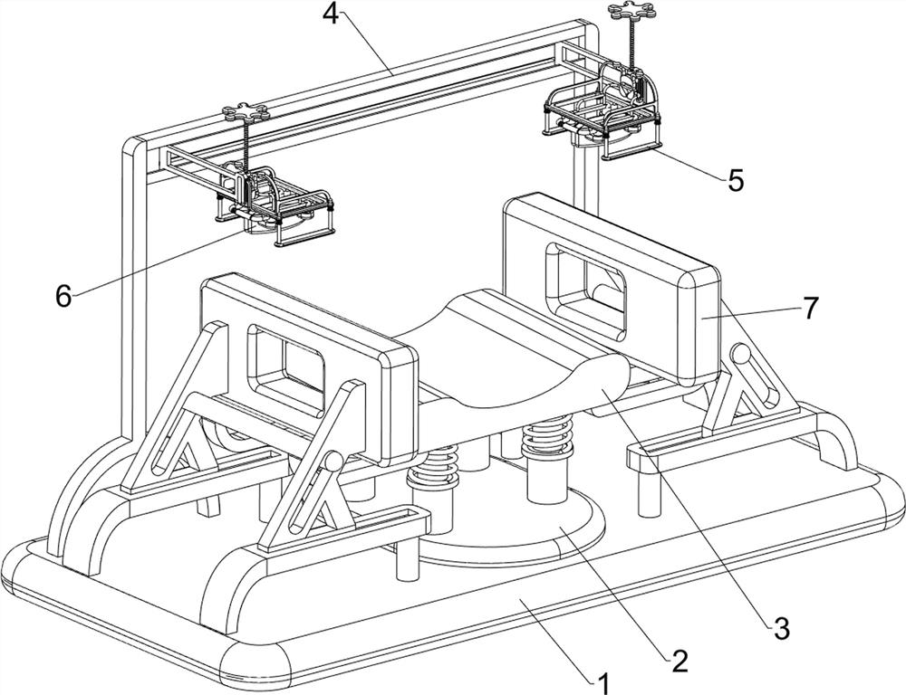
[0071]An eyelid fixation device for hospital ophthalmology, such as figure 1 As shown, it includes a base plate 1, a mounting seat 2, a headrest assembly 3, an adjustment assembly 4, a limit frame assembly 5 and an eyelid fixing assembly 6. The top of the base plate 1 is provided with a mounting seat 2, and the top of the mounting seat 2 is provided with a headrest assembly. 3. An adjustment component 4 is arranged on the rear side of the top of the bottom plate 1 , a limiter component 5 is arranged on the adjustment component 4 , and an eyelid fixing component 6 is arranged on the limiter component 5 .
[0072] When the user's eyelid needs to be fixed, the staff can place the head on the headrest assembly 3, and then adjust the adjustment assembly 4 to drive the limit frame assembly 5 and the eyelid fixing assembly 6 to move. When in position, the adjusting component 4 can be rotated, thereby driving the limiting frame component 5 and the eyelid fixing component 6 to move dow...
Embodiment 2
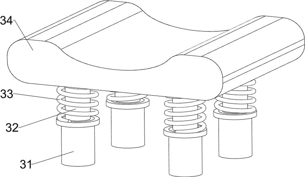
[0074] On the basis of Example 1, as Figure 3-Figure 7 As shown, the headrest assembly 3 includes a hollow column 31, a support rod 32, a first spring 33 and a pillow 34. The top, front and rear sides of the mounting seat 2 are provided with a left and right symmetrical hollow column 31, and a support rod is slidably arranged in the hollow column 31. 32. A pillow 34 is connected between the top of the support rod 32, and a first spring 33 is connected between the bottom of the pillow 34 and the hollow column 31.
[0075] The user can place their head on the pillow 34, the downward movement of the pillow 34 drives the support rod 32 to move downward in the hollow column 31, the first spring 33 is compressed, and the first spring 33 can play a buffering role to increase the comfort of the user. Then, the adjusting component 4 can be adjusted, so as to drive the limiter component 5 and the eyelid fixing component 6 to be positioned under the user's eyes, and then the eyelid fixi...
Embodiment 3
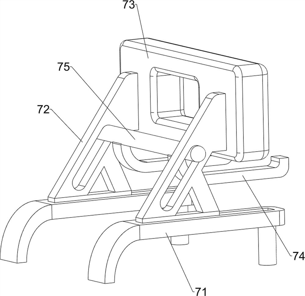
[0083] On the basis of Example 2, as Figure 8 As shown, it also includes a head restraint assembly 7. The head restraint assembly 7 includes a fixed guide rail frame 71, a sliding slotted support frame 72, a soft limit block 73, a second connecting frame 74 and a sliding rod 75. The bottom plate 1 Two fixed guide rail frames 71 are connected on both sides of the top, the top of the fixed guide rail frame 71 is slidably provided with a sliding slotted support frame 72 , and a sliding rod is slidably connected between the inner walls of the sliding slotted support frame 72 on the front and rear sides. 75 , a soft stop block 73 is connected between the upper part of the sliding slotted support frame 72 on the front and rear sides, and a second connecting frame 74 is connected between the bottom of the sliding rod 75 and the bottom of the pillow 34 .
[0084] When the user's head rests on the pillow 34, the pillow 34 moves downward through the second connecting frame 74 to drive ...
PUM
 Abstract
Description
Claims
Application Information
 - R&D
- Intellectual Property
- Life Sciences
- Materials
- Tech Scout
- Unparalleled Data Quality
- Higher Quality Content
- 60% Fewer Hallucinations
Browse by: Latest US Patents, China's latest patents, Technical Efficacy Thesaurus, Application Domain, Technology Topic, Popular Technical Reports.
© 2025 PatSnap. All rights reserved.Legal|Privacy policy|Modern Slavery Act Transparency Statement|Sitemap|About US| Contact US: help@patsnap.com


