A dual-flow rail transit vehicle control system and method

A rail transit vehicle and control system technology, which is applied in the field of dual-stream rail transit vehicle control systems, and can solve problems such as vehicle high-voltage components or vehicle damage, and vehicle high-voltage circuit aggressiveness

Active Publication Date: 2022-07-08
CHONGQING CRRC RAILWAY VEHICLES CO LTD
View PDF23 Cites 0 Cited by
  • Summary
  • Abstract
  • Description
  • Claims
  • Application Information

AI Technical Summary

Problems solved by technology

[0007] When the dual-current vehicle is working under different power grids, it is necessary to switch the AC and DC circuits. If the switch is wrong, it will cause the risk of the high-voltage circuit of the vehicle under different power grids.
Rush forward means that when the DC high voltage enters the AC high voltage circuit or the AC high voltage penetrates into the DC high voltage circuit, this situation may cause great damage to the high voltage components of the vehicle or the vehicle

Method used


Image

  • A dual-flow rail transit vehicle control system and method
  • A dual-flow rail transit vehicle control system and method
  • A dual-flow rail transit vehicle control system and method

Examples


Embodiment

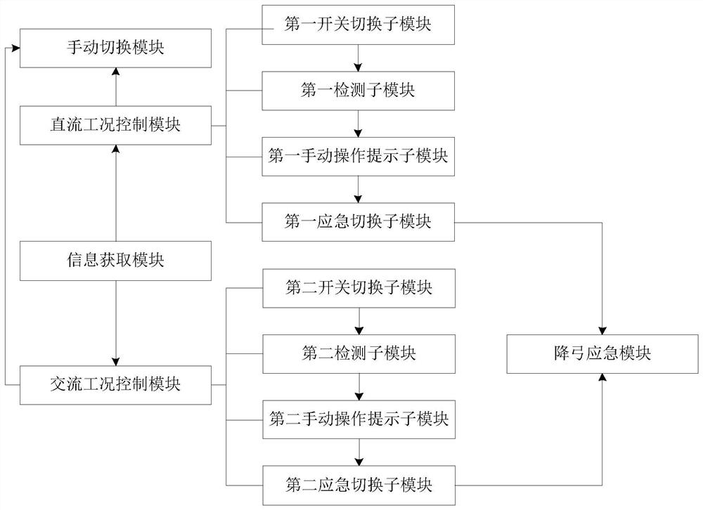
[0070] A dual-flow rail transit vehicle control system, basically as attached figure 1 Shown: Includes:

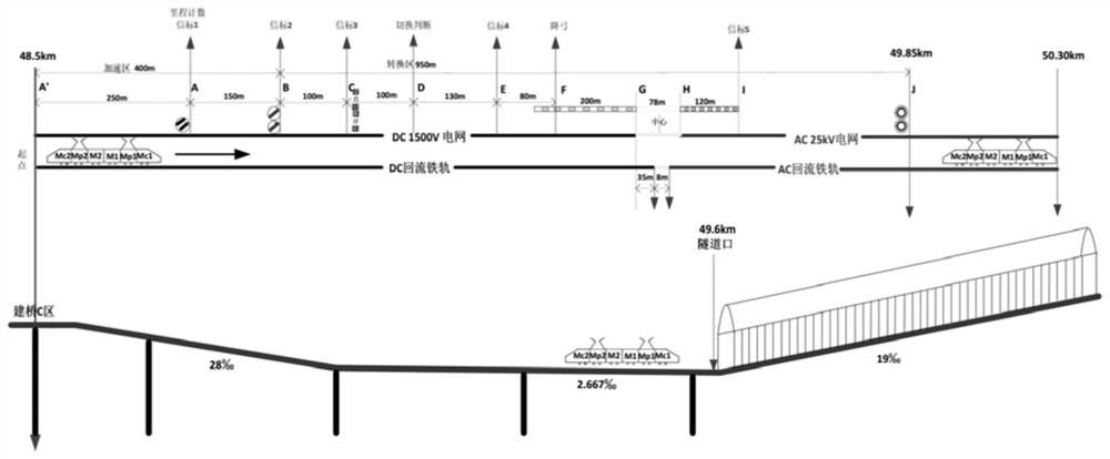
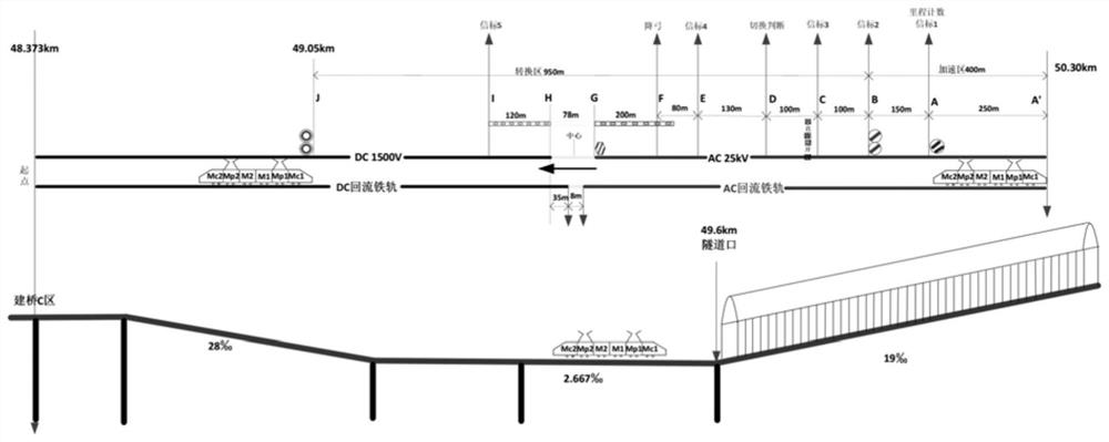
[0071] Information acquisition module: used to acquire the AC-DC switching instruction when the rail vehicle reaches the DC power supply area or the switching area of ​​the AC power supply area; the switching area includes the initial beacon point, the control position beacon point and the completion position beacon point. The DC switching command includes the initial position subcommand corresponding to the initial beacon point, the control bit subcommand corresponding to the control bit beacon point, and the completion bit subcommand corresponding to the completion bit beacon point; such as figure 2 , image 3 As shown, in this embodiment, the switching area is the area between the ground beacon 1 and the ground beacon 5 . In this solution, the AC / DC switching instruction is specifically obtained at the position of the ground beacon 1 . About ground beacons. As the p...

Embodiment 2

[0114] The difference between the second embodiment and the first embodiment is that the system further includes the following modules:

[0115] Fault collection and storage module: used to collect, organize and store the fault information of the rail vehicle in motion, the fault information includes a regular fault table and a switching fault table, and both the regular fault table and the switching fault table include the fault name, fault cause , fault resolution measures and fault level.

[0116] Fault protection module: It is used to collect fault information stored in the storage module for fault protection when it is detected that the rail vehicle has a fault in AC-DC switching.

[0117] Partial fault removal module: It is used to disconnect all or part of the rail vehicle corresponding to the abnormal fault from the power supply circuit when an abnormal fault of the rail vehicle is detected, and use a sound unit train to pull the whole train back to the vehicle base. ...


PUM


Abstract

The present invention relates to the technical field of rail traffic control, in particular to a dual-flow rail traffic vehicle control system and method. The method is applied to the system. or the switching area of ​​the AC power supply area, obtain the AC / DC switching command; the DC working condition control module: used to generate the first initial prompt information; also used to cut off the DC power supply circuit of the rail vehicle according to the control position sub-command; also used to connect the track The AC power supply circuit of the vehicle; the AC working condition control module: used to generate the second initial prompt information; also used to cut off the AC power supply circuit of the rail vehicle according to the control position sub-command; and also used to connect the DC power supply circuit of the rail vehicle. The present invention can perform precise AC-DC circuit switching for dual-flow vehicles, and avoid the risk of high-voltage circuits of dual-flow vehicles running in different power grids, thereby causing great damage to vehicle high-voltage devices or vehicles.

Description

technical field [0001] The invention relates to the technical field of rail traffic control, in particular to a dual-flow rail traffic vehicle control system and method. Background technique [0002] Traction power supply system refers to the current system, voltage level and power supply method used by the power supply system to supply power to electric vehicles or electric locomotives. It is generally regarded as an advanced traction power supply system and has formed a national standard. Mainly for single-phase power frequency 25kV AC system and DC traction power supply system. [0003] Single-phase power frequency 25kV AC system is generally suitable for trunk electrified railways with large capacity, heavy load, high speed and long transportation distance, such as common-speed passenger-cargo railroads, 200-250km / h passenger-cargo railroads or passenger-dedicated lines , 300km / h and above high-speed railway or passenger dedicated line, and has basically formed a techn...

Claims


Application Information

Patent Timeline
Patent Type & Authority Patents(China)
IPC IPC(8): B60M3/00
CPCB60M3/00
Inventor 王永伟赵洪涛孙文斌刘正威姚平姚鸿洲陈波赵益林张鸿艳
Owner CHONGQING CRRC RAILWAY VEHICLES CO LTD
Why Eureka
Try Eureka