Lifting device

A lifting device and driving device technology, which is applied in the direction of lifting devices, lifting frames, etc., can solve the problems of high safety risk factor, high cost of screw jacking mechanism, high center height of equipment and products, etc.

Active Publication Date: 2021-07-02
JIANGSU SHENMA ELECTRIC CO LTD
View PDF8 Cites 3 Cited by
  • Summary
  • Abstract
  • Description
  • Claims
  • Application Information

AI Technical Summary

Problems solved by technology

However, the cost of the screw jacking mechanism is high, the space occupied by the height is

Method used


Image

  • Lifting device
  • Lifting device
  • Lifting device

Examples


Embodiment Construction

[0019] As required, specific embodiments of the invention will be disclosed herein. However, it should be understood that the embodiments disclosed herein are merely typical examples of the invention, which can be embodied in various forms. Therefore, specific details disclosed herein are not to be considered limiting, but merely as a basis for the claims and as a representative basis for teaching one skilled in the art to variously employ the invention in any appropriate way in practice, This includes taking various features disclosed herein and combining features that may not be expressly disclosed herein.

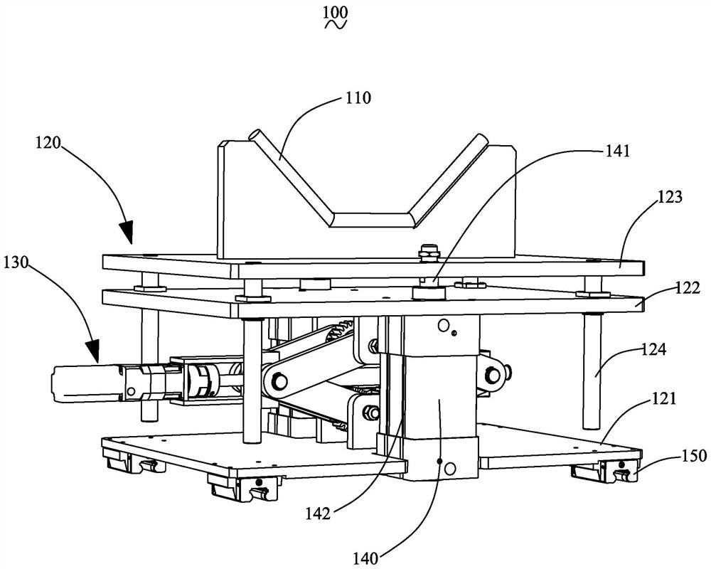
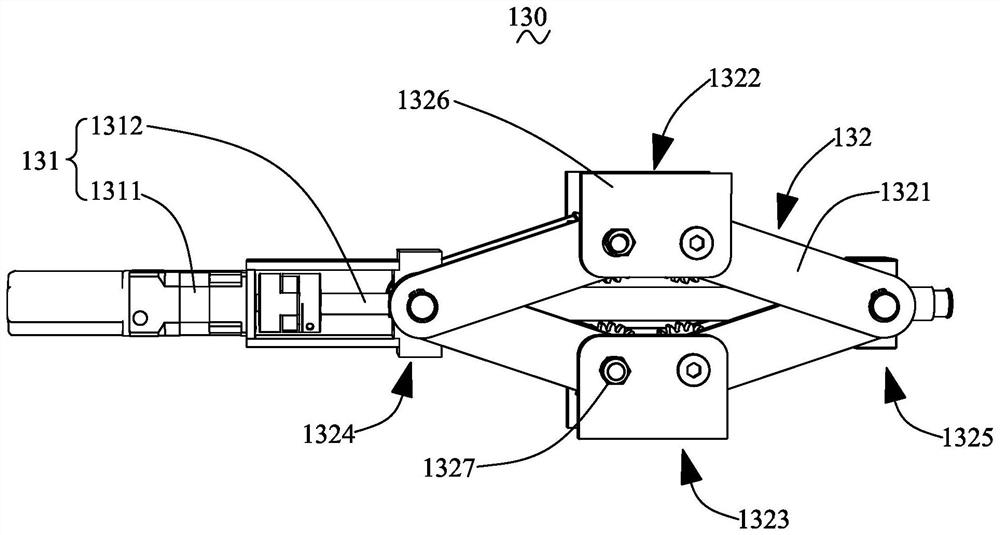
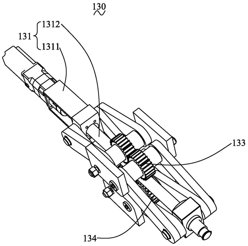
[0020] Such as figure 1 As shown, this embodiment provides a lifting device 100 for supporting and lifting insulators, including a lifting assembly 120 and a supporting assembly 110. The lifting assembly 120 includes a bottom plate 121, two The first-level jacking panel 122 and the first-level jacking panel 123, the guide rod 124 passes through the first-level jacking ...


PUM


Abstract

The invention discloses a lifting device which is used for bearing and lifting an insulator and comprises a lifting assembly and a bearing assembly. The lifting assembly comprises a bottom plate, a second-stage jacking panel and a first-stage jacking panel which are arranged in parallel from bottom to top; guide rods sequentially penetrates through the first-stage jacking panel and the second-stage jacking panel and is fixed onto the second-stage jacking panel; a second-stage driving device is arranged between the bottom plate and the second-stage jacking panel to drive the second-stage jacking panel to move in the direction of the guide rods; a first-stage driving device is arranged between the second-stage jacking panel and the first-stage jacking panel to drive the first-stage jacking panel to move in the direction of the guide rods; and the bearing assembly is arranged on the first-stage jacking panel. According to the lifting device, the first-stage jacking panel and the second-stage jacking panel are matched, the first-stage jacking panel is driven to be used for avoiding the height of an umbrella skirt of an insulator product, the second-stage jacking panel does not need to be adjusted or driven for products with the same specification, and the first-stage jacking panel is adjusted to adapt to products with different specifications, so that the adjusting stroke of the lifting device can be reduced, and working efficiency is improved.

Description

technical field [0001] The invention relates to the field of manufacturing power transmission insulation equipment, in particular to a lifting device. Background technique [0002] The purpose of the lifting device is to accept the insulator products with shed sheaths that have been injected on the cutting machine, lift them to the height specified by the system according to the product specifications, and then the cutting mechanism cuts the sheaths at both ends of the insulator. [0003] At present, most lifting devices in this industry use screw jacking mechanisms to lift insulator products with different diameters. However, the cost of the screw jacking mechanism is high, the space occupied by the height is large, the center height of the equipment product is high, and the safety risk factor is high. Contents of the invention [0004] Aiming at the deficiencies of the prior art, the object of the present invention is to provide a lifting device, the lifting device adop...

Claims


Application Information

Patent Timeline
IPC IPC(8): B66F7/06B66F7/28B66F7/20
CPCB66F7/0608B66F7/28B66F7/20
Inventor 陆久云孙银建赵建余
Owner JIANGSU SHENMA ELECTRIC CO LTD
Why Eureka
Try Eureka