
Power cable withstand voltage test detection equipment

A technology of withstand voltage test and detection equipment, applied in the parts of electrical measuring instruments, measuring electricity, measuring devices, etc., can solve the problem of inability to meet the needs of different types of cable detection, and achieve the effect of changing the radius

Active Publication Date: 2021-07-02
STATE GRID HEBEI ELECTRIC POWER CO LTD +1
View PDF13 Cites 0 Cited by
  • Summary
  • Abstract
  • Description
  • Claims
  • Application Information

AI Technical Summary

Problems solved by technology

When the existing detection equipment detects cables, most of them can only detect cables with a single radius and length, which cannot meet the detection needs of different types of cables

Method used


Image

  • Power cable withstand voltage test detection equipment
  • Power cable withstand voltage test detection equipment
  • Power cable withstand voltage test detection equipment

Examples


Embodiment 1

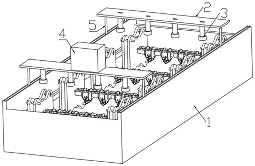
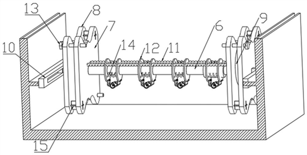
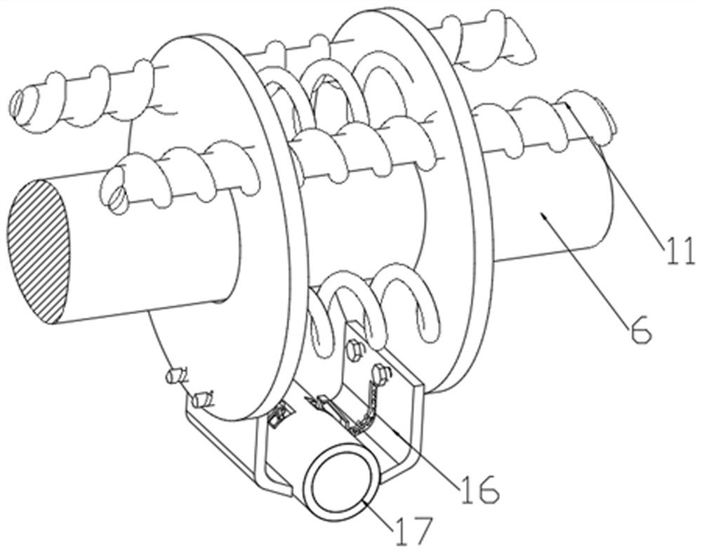
[0025] see Figure 1-4 , in an embodiment of the present invention, a power cable withstand voltage test and detection equipment mainly includes a heat preservation room 1 .

[0026] The heat preservation chamber 1 is provided with a constant temperature tank, and the upper side of the heat preservation chamber 1 is symmetrically provided with a plurality of sliding grooves and a plurality of sliding rods 5 that can be slidably connected with the sliding grooves, and the tops of every two sliding rods 5 are installed There is a top plate 2, and a plurality of through holes are opened on the top plate 2 on the front side, the bottom end of the through holes is connected with a wire barrel, and the other end of the wire barrel is connected with a plug-in wire for clamping the connection port of the test line Connector 3, the upper side of the top plate 2 on the rear side is equipped with a tester 4 for applying current to the test cable, and the output end of the tester 4 is als...

Embodiment 2

[0029] see Figure 1-4 , in an embodiment of the present invention, a power cable withstand voltage test and detection equipment mainly includes a heat preservation room 1 .

[0030] The heat preservation chamber 1 is provided with a constant temperature tank, and the upper side of the heat preservation chamber 1 is symmetrically provided with a plurality of sliding grooves and a plurality of sliding rods 5 that can be slidably connected with the sliding grooves, and the tops of every two sliding rods 5 are installed There is a top plate 2, and a plurality of through holes are opened on the top plate 2 on the front side, the bottom end of the through holes is connected with a wire barrel, and the other end of the wire barrel is connected with a plug-in wire for clamping the connection port of the test line Connector 3, the upper side of the top plate 2 on the rear side is equipped with a tester 4 for applying current to the test cable, and the output end of the tester 4 is als...


PUM


Abstract

The invention relates to the field of power equipment detection, and in particular relates to power cable withstand voltage test detection equipment which comprises a heat preservation chamber, a thermostatic bath is arranged in the heat preservation chamber, a plurality of fixed insertion rods are arranged on the inner walls of the left side and the right side of the thermostatic bath, a sliding plate is arranged at the other end of each fixed insertion rod, the sliding plate is provided with a sliding groove and a fixing rod which can match the sliding groove and connected with the sliding groove in a front-back sliding mode, the thermostatic bath is connected with a second mounting plate through the fixing rod, two fixing bolts are arranged on the second mounting plate in a threaded mode, the fixing bolts are further connected with a first mounting plate in a threaded mode, the first mounting plate is provided with a plurality of cross-shaped slots which can be in matched insertion connection with cross-shaped clamping rings, and a rotating motor is further mounted between the first mounting plate and the second mounting plate. The detection equipment is simple in structure, and cables with different lengths and radiuses can be tested according to needs.

Description

technical field [0001] The invention relates to the field of power equipment detection, in particular to a power cable withstand voltage test detection device. Background technique [0002] The withstand voltage test of the finished cable is an AC voltage test, also called a power frequency withstand voltage test. AC withstand voltage test is in [0003] On the insulation of the finished wire and cable, apply a voltage value that is a certain multiple of the working voltage and keep it for a certain period of time to check whether the insulation is broken down. For insulated wires and cables for power transmission, this test must be carried out for each product before leaving the factory. When the existing detection equipment detects cables, most of them can only detect cables with a single radius and length, which cannot meet the detection needs of cables of different types. [0004] Therefore, in view of the above status quo, it is urgent to develop a power cable withst...

Claims


Application Information

Patent Timeline
Patent Type & Authority Applications(China)
IPC IPC(8): G01R31/12G01R1/04
CPCG01R31/1272G01R1/0425
Inventor 杨鹏王学彬赵春雷王磊宋文乐
Owner STATE GRID HEBEI ELECTRIC POWER CO LTD
Learn More