Disc type permanent magnet transmission device with slotted back iron

A permanent magnet transmission device and disc type technology, applied in the transmission field, can solve the problems of obvious magnetic leakage and low utilization rate of magnetic energy, and achieve the effects of easy installation and operation, saving production costs, and facilitating mass production and manufacturing.

Active Publication Date: 2021-07-02
HEFEI UNIV OF TECH
View PDF4 Cites 0 Cited by
  • Summary
  • Abstract
  • Description
  • Claims
  • Application Information

AI Technical Summary

Problems solved by technology

[0004] Aiming at the problems in the prior art, the present invention provides a disc-type permanent magnet transmission device with slotted back iron, which overcomes the defects of obvious magnetic leakage on the side of the existing disc-type magnetic coupling and low utilization rate of magnetic energy

Method used


Image

  • Disc type permanent magnet transmission device with slotted back iron
  • Disc type permanent magnet transmission device with slotted back iron
  • Disc type permanent magnet transmission device with slotted back iron

Examples


Embodiment 1

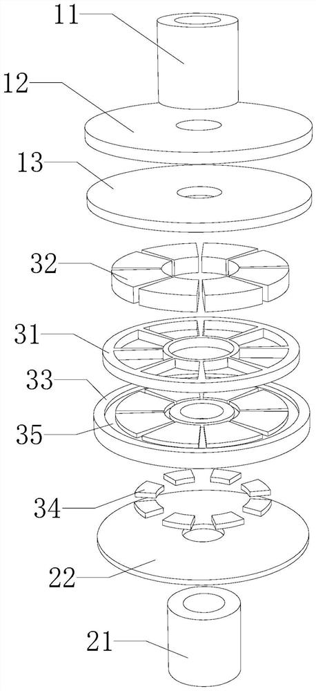
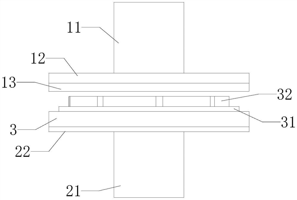
[0034] Such as figure 1 , figure 2 As shown, this embodiment provides a disc-type permanent magnet transmission device with slotted back iron, which is used to transmit power between two shafts. The two shafts include shaft one 11 and shaft two 21 . The first shaft 11 and the second shaft 21 are arranged coaxially. The transmission device includes: a top plate 12 , a vortex plate 13 , a chassis 22 , and a fixing mechanism 3 .

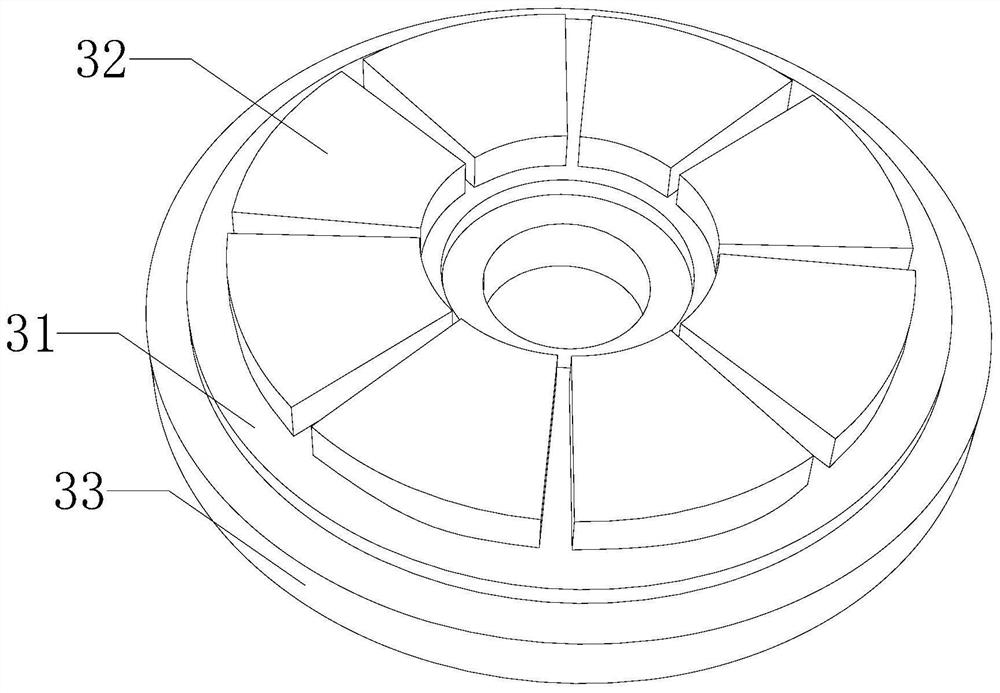
[0035] Please combine image 3 , in this embodiment, in order to facilitate installation, through holes are opened in the middle of the first shaft body 11, the top plate 12, the vortex disc 13, the installation plate 33, the chassis 22 and the second shaft body 21, and a plurality of the The inner diameters of the through holes are all equal. The outer diameters of the top plate 12 , the swirl plate 13 , the mounting plate 33 and the bottom plate 22 are all equal. The top plate 12 is coaxially fixed on the side of the shaft body 11 facing the sh...

Embodiment 2

[0046] see Figure 9 , this embodiment provides an installation method, which can be applied to the disc-type permanent magnet transmission device with slotted back iron in Embodiment 1. The installation methods include:

[0047] Step S1: Firstly arrange the shaft body 1 and the top plate 12 coaxially, and then fix the shaft body 1 11 and the top plate 12 through welding or other means.

[0048] Step S2: First, the top plate 12 and the vortex plate 13 are arranged coaxially, and then the vortex plate 13 and the top plate 12 are fixedly connected by gluing or the like.

[0049] Step S3: First, the chassis 22 and the shaft body 2 21 are coaxially arranged, and then the chassis 22 and the shaft body 2 21 are fixedly connected by means of welding or the like.

[0050] Step S4: First classify and embed a plurality of auxiliary magnetic poles 34 in the plurality of installation slots 36 on the installation disk 33 at intervals, then set the installation disk 33 coaxially with the ...

Embodiment 3

[0054] The difference between this embodiment and Embodiment 1 is that this embodiment has an additional shell on the basis of the existing structure of Embodiment 1. The shell includes: shell one and shell two.

[0055] Shell 1 and shell 2 are set separately. Wherein, the shaft body one 11, the top plate 12 and the swirl plate 13 can all be installed inside the shell one. The shaft body 2 21, the chassis 22 and the fixing mechanism 3 can all be installed inside the shell 2. Shell 1 and shell 2 can also be made of paramagnetic lightweight materials, which can protect the entire transmission device and the two shafts, prevent dust from entering the internal structure of the transmission device, and prevent external objects from colliding with the internal structure. It can also reduce the oxidation and aging degree of the internal structure of the transmission device, thereby prolonging the service life of the transmission device. In this embodiment, both the first shell and...


PUM


Abstract

The invention relates to the technical field of transmission, in particular to a disc type permanent magnet transmission device with slotted back iron, which is used for transmitting power between two shaft bodies. The two shaft bodies comprise a first shaft body and a second shaft body. The first shaft body and the second shaft body are coaxially arranged. The transmission device comprises a top disc, a vortex disc, a bottom disc and a fixing mechanism. The top disc is coaxially fixed to one side of the first shaft body. The vortex disc is coaxially fixed to the side, facing the second shaft body, of the top disc. The bottom disc is coaxially fixed to the side, facing the first shaft body, of the second shaft body. The fixing mechanism is arranged on the side, facing the first shaft body, of the bottom plate. The fixing mechanism comprises a mounting frame, a plurality of main magnetic poles, a mounting disc and a plurality of auxiliary magnetic poles. The mounting disc is fixed to the side, facing the first shaft body, of the bottom disc. A first mounting groove is formed in one side of the mounting disc, and a plurality of second mounting grooves corresponding to the auxiliary magnetic poles are annularly formed in the other side of the mounting disc around the center axis of the mounting disc. Side magnetic leakage existing in a traditional disc type magnetic coupling is effectively reduced, and then the torque capable of being transmitted by the transmission device is improved.

Description

technical field [0001] The invention relates to the technical field of transmission, in particular to a disc-type permanent magnet transmission device with slotted back iron. Background technique [0002] Coupling refers to a device that connects two shafts or shafts and rotating parts, and rotates together during the transmission of motion and power, and does not disengage under normal conditions. The magnetic coupling is also used as a safety device to prevent the motor from being locked due to the excessive load of the connected parts, and it plays the role of overload protection. [0003] The existing disc-type magnetic coupling structure inevitably has side flux leakage. When the size of the coupling increases, the side flux leakage becomes more obvious and the utilization rate of magnetic energy decreases. Contents of the invention [0004] Aiming at the problems in the prior art, the present invention provides a disc-type permanent magnet transmission device with s...

Claims


Application Information

Patent Timeline
Patent Type & Authority Applications(China)
IPC IPC(8): H02K49/10
CPCH02K49/108
Inventor 郑红梅田文立史洪扬陈科殷磊刘志杰郑明睿
Owner HEFEI UNIV OF TECH
Why Eureka
Try Eureka