Subsonic aircraft air inlet channel

An air intake and aircraft technology, which is applied to the combustion of the air intake of the power unit, aircraft parts, and power units on the aircraft. Boundary layer, poor performance, etc.

Pending Publication Date: 2021-07-06
上海甘石星经智能科技有限公司
View PDF2 Cites 1 Cited by
  • Summary
  • Abstract
  • Description
  • Claims
  • Application Information

AI Technical Summary

Problems solved by technology

Due to the excellent comprehensive performance of the inlet without boundary layer, it has been widely used in the inlet of subsonic aircraft, especially the unmanned aircraft that focus on stealth and drag reduction, such as the X-45A and X-45C of the United States. , but because there is no boundary layer partition, this kind of inlet cannot completely exclude the incoming bo

Method used


Image

  • Subsonic aircraft air inlet channel
  • Subsonic aircraft air inlet channel
  • Subsonic aircraft air inlet channel

Examples


Embodiment 1

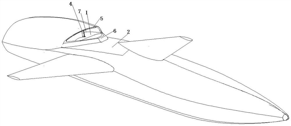
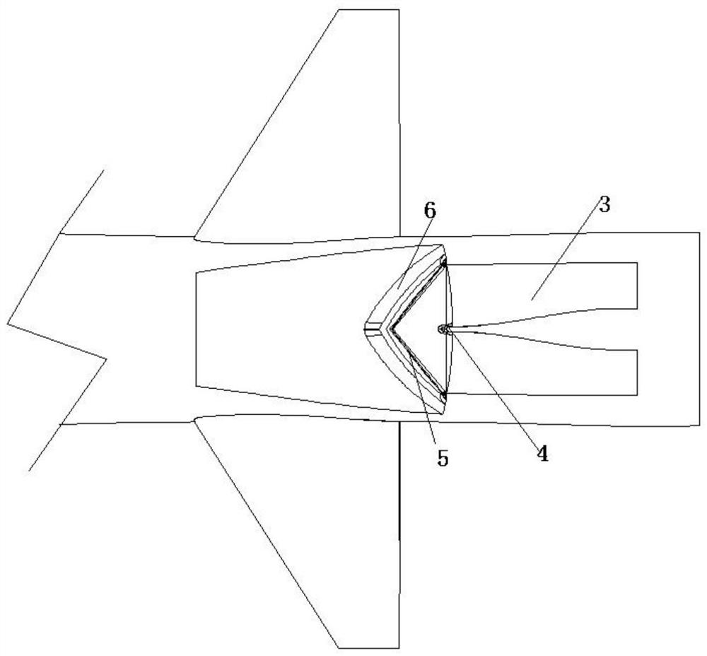
[0018] Such as figure 1 The air inlet of a subsonic aircraft is shown as an air inlet of a subsonic aircraft, including an air inlet surface 1, the bottom of which air inlet surface 1 is connected to a fuselage 2, and integrated with the fuselage 2, The rear end of the air inlet surface 1 is connected to the inner channel 3 of the air inlet, and the internal support of the inner channel 3 of the air inlet is fixed with a cutoff plate 4, and the mouth surface 1 of the air inlet is surrounded by a lip cover 5, and the air inlet The front side of the crossing surface 1 is provided with a quasi-triangular step compression surface 6, the triangular-like step compression surface 6 is fixed on the fuselage 2, and the lip cover 5 is smoothly connected with the fuselage 2 and the triangular-like step compression surface 6.

Embodiment 2

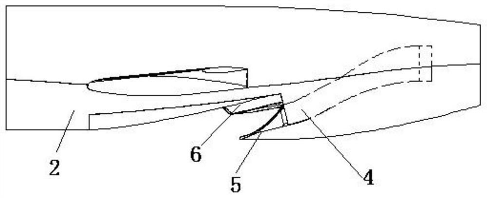
[0020] Such as Figure 1-Figure 4 The air inlet of a subsonic aircraft shown includes an air inlet surface 1, the bottom of the air inlet surface 1 is connected to the fuselage 2, and the shape of the air inlet surface 1 is determined according to the shape of the fuselage 2, And integrated with the fuselage 2, the rear end of the air inlet surface 1 communicates with the inner passage 3 of the air inlet, and the inner passage 3 of the air inlet includes an inner pipe 7 bent and extended toward the inside of the fuselage, and the inner pipe 7. The rear end is connected to the outlet surface 8 of the air inlet, and the front end is connected to the mouth surface 1 of the air inlet. The inner channel 3 of the air inlet is supported and fixed with a cutoff plate 4, and the flow divider 4 not only increases the structure of the inner passage 3 of the air inlet. Intensity, the airflow captured by the inlet surface 1 can also be divided into two streams in the inner channel 2 of the...


PUM


Abstract

The invention discloses a subsonic aircraft air inlet channel which comprises an air inlet channel opening face, the bottom of the air inlet channel opening face is connected with an aircraft body and is integrally fused with the machine body, the rear end of the air inlet channel opening face communicates with an air inlet channel inner channel, a flow separation plate is fixedly supported in the air inlet channel inner channel, and the air inlet channel opening face is surrounded by a lip cover; the front side of the air inlet opening face is provided with a similar triangular step compression surface, the similar triangular step compression surface is fixed on the machine body, and the lip cover is in smooth connection with the machine body and the similar triangular step compression surface. According to the structure, a boundary layer separation channel independently arranged on the machine body is canceled, and a bulge protruding out of the surface of the machine body is replaced by the similar triangular step compression surface; meanwhile, by means of integrated fusion of the sweepback lip cover, the air inlet channel opening face, the similar triangular step compression face and the machine body, the boundary layer of the machine body can be effectively eliminated, the high total pressure recovery coefficient and the low flow field distortion index of the air inlet channel are kept, and meanwhile the attack angle and sideslip angle characteristics of the air inlet channel can be considered.

Description

technical field [0001] The invention relates to the technical field of aircraft design, in particular to an air inlet of a subsonic aircraft. Background technique [0002] As the "breather" of the air-breathing propulsion system, the intake is responsible for capturing, compressing, and rectifying the airflow. Its design features and working characteristics have a significant impact on the engine's working efficiency. Subsonic aircraft is the most widely used type of air-breathing aircraft, and the inlets of its power system generally have pitot-type inlets, S-curved inlets, and buried inlets. Considering factors such as engine installation and inlet performance, most modern advanced subsonic aircraft use S-curved inlets. [0003] In order to prevent the air inlet from inhaling the low-energy flow in the boundary layer of the fuselage surface, the traditional S-curved air inlet usually lifts the inlet of the air inlet from the surface of the fuselage by setting special boun...

Claims


Application Information

Patent Timeline
IPC IPC(8): B64D33/02
CPCB64D33/02B64D2033/0253
Inventor 张洪雷林景
Owner 上海甘石星经智能科技有限公司
Why Eureka
Try Eureka