Side formwork structure of deep foundation and its construction method

A construction method and deep foundation technology, applied in foundation structure engineering, soil protection, construction, etc., can solve the problems that the construction quality and safety of the side formwork of the deep foundation cannot meet the construction requirements, and achieve the improvement of the cantilever force system, Ensure the construction quality and reduce the thickness

Active Publication Date: 2022-07-15
SHANGHAI NO 4 CONSTR
View PDF0 Cites 0 Cited by
  • Summary
  • Abstract
  • Description
  • Claims
  • Application Information

AI Technical Summary

Problems solved by technology

[0004] The purpose of the present invention is to provide a side formwork structure for a deep fall foundation and its construction method, so as to solve the problem that the construction quality and safety of the existing side form for a deep fall foundation cannot meet the construction requirements

Method used


Image

  • Side formwork structure of deep foundation and its construction method
  • Side formwork structure of deep foundation and its construction method
  • Side formwork structure of deep foundation and its construction method

Examples


Embodiment 1

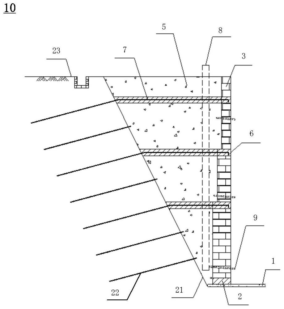
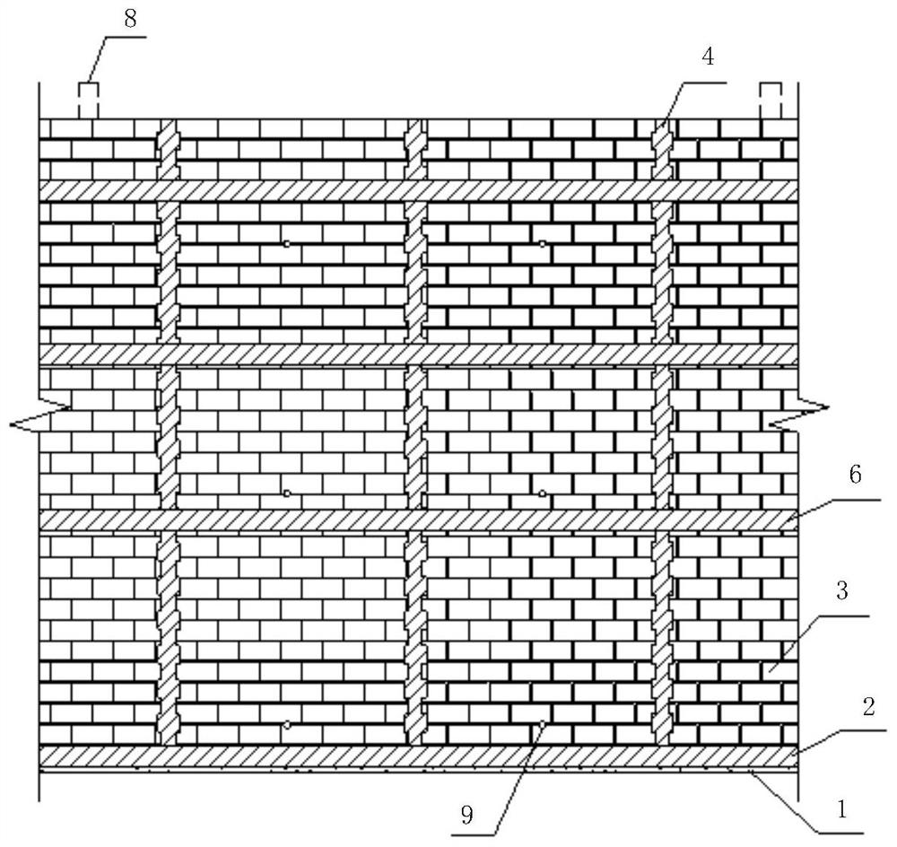
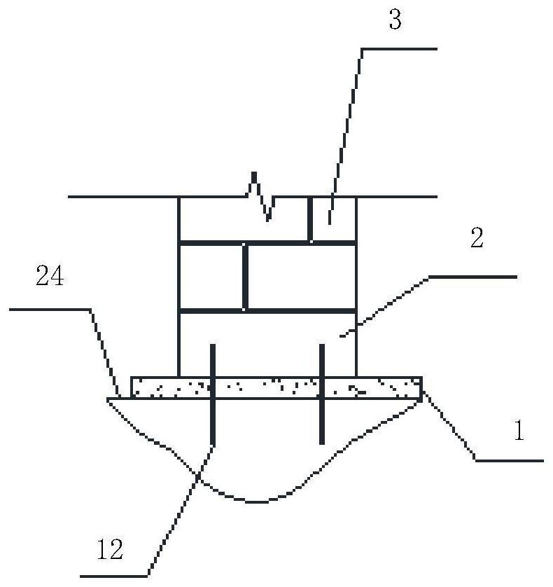
[0051] Please refer to figure 1 and figure 2 , which is a schematic structural diagram of the side mold structure of the drop-depth foundation according to the first embodiment of the present invention. like figure 1 and figure 2As shown, the side formwork structure 10 of the deep foundation includes: a concrete cushion 1, a foundation beam 2, a brick tire form 3, a structural column 4, a backfill soil layer 5, a ring beam 6 and a partition strip 7; the The concrete cushion 1 is arranged on the bottom surface of the foundation pit, the foundation beam 2 is fixed on the concrete cushion 1 and is continuously arranged along the surrounding edges of the concrete cushion 1, and the brick tire mold 3 is built on the concrete cushion 1. On the foundation beam 2, the structural column 4 is longitudinally arranged in the plane of the brick tire mold 3 and is integrated with the brick tire mold 3; the backfill soil layer 5 and the partition plate belt 7 are both It is arranged be...

Embodiment 2

[0078] Please refer to figure 2 and Image 6 , which is a schematic structural diagram of the side mold structure of the drop-depth foundation according to the second embodiment of the present invention. like figure 1 and figure 2 As shown, the side formwork structure 10 of the deep foundation includes: a concrete cushion 1, a foundation beam 2, a brick tire form 3, a structural column 4, a backfill soil layer 5, a ring beam 6 and a partition strip 7; the The concrete cushion 1 is arranged on the bottom surface of the foundation pit, the foundation beam 2 is fixed on the concrete cushion 1 and is continuously arranged along the surrounding edges of the concrete cushion 1, and the brick tire mold 3 is built on the concrete cushion 1. On the foundation beam 2, the structural column 4 is longitudinally arranged in the plane of the brick tire mold 3 and is connected with the brick tire mold 3; the backfill soil layer 5 and the partition plate belt 7 are both. It is arranged ...


PUM


Abstract

The invention provides a side formwork structure of a drop-deep foundation and a construction method thereof, wherein the side-form structure of a drop-deep foundation comprises: a concrete cushion layer, a foundation beam, a brick tire form, a structural column, a backfill soil layer, a ring beam and a Partition plate belt; concrete cushion, foundation beam, brick tire mold and structural column are arranged in sequence on the bottom surface of the foundation pit, one end of the partition plate belt is fixed with the supporting structure of the foundation pit, and the other end is fixed with the ring beam. Separate backfill layers. In the side formwork structure of the drop-depth foundation and the construction method thereof provided by the present application, the structural columns and reinforced concrete ring beams are arranged in the brick tire mold to strengthen the overall rigidity and stability of the brick tire membrane structure, and according to the brick tire mold The height of the formwork is set with several partition plates to cut off the pressure of the upper backfill to the lower backfill, thereby reducing the lateral pressure of the backfill to the brick mold, which can not only ensure the construction quality and improve the safety, but also can Reduce the thickness of the brick tire mold to achieve the purpose of reducing costs and increasing efficiency.

Description

technical field [0001] The invention relates to the technical field of building construction, in particular to a side formwork structure of a drop-deep foundation and a construction method thereof. Background technique [0002] In the foundation pit project, in order to bury the raft foundation of the main building and the foundation of the elevator and other equipment, a "pit in a pit" is usually dug deep inside the large foundation pit independently. At present, the following two forms are widely used for the side formwork of the deep foundation in the "pit-in-pit": one is to directly use the supporting structure as the side form, such as row piles, grading rock walls, soil nail walls, etc. The surface of the protective body is uneven, and the quality cannot be guaranteed when the external waterproofing is constructed on it, and the risk of system leakage is high; the second is to construct the brick tire mold in the pit, as the base layer of the external waterproofing and...

Claims


Application Information

Patent Timeline
Patent Type & Authority Patents(China)
IPC IPC(8): E02D27/01E02D27/44E02D3/10
CPCE02D27/01E02D27/44E02D3/10
Inventor 符伟猜段博马天雨滕世华陈泱源
Owner SHANGHAI NO 4 CONSTR
Why Eureka
Try Eureka