Vacuum pipe and refrigerator

A technology of vacuum tubes and inner tubes, which is applied in the field of refrigeration and freezing devices, and can solve problems such as inability to satisfy users to adjust the position of the refrigerator, complex process, and large volume.

Active Publication Date: 2021-07-06
QINGDAO HAIER REFRIGERATOR CO LTD +1
7 Cites 0 Cited by

AI-Extracted Technical Summary

Problems solved by technology

[0002] The traditional stand-alone refrigerator integrates the refrigeration system and the box body. Usually the refrigeration system needs to occupy a large volume, resulting in a limited internal volume of the box body, and because the box body usually needs to make way for th...

Method used

As shown in Figure 1, in some embodiments, end seal 803 is respectively formed with nickel-plated layer 841 on its inner and outer surfaces; The sheet 842 is welded by the nickel-plated layer 841 and the solder sheet 842 to realize the sealing and fixing of the end sealing member 803 and the outer tube 801 and the inner tube 802 . The nickel-plated layer 841 is respectively formed on the inner and outer surfaces of the end sealing member 803, and then the nickel-plated layer 841, the solder sheet 842 Welding realizes the sealing and fixing of the end sealing member 803 and the outer tube 801 and inner tube 802, so that the end sealing member 803, the outer tube 801 and the inner tube 802 can be tightly sealed to avoid air leakage caused by poor sealing. The solder sheet 842 can be, for example, a silver-copper solder sheet, Ag:Cu=72:28. The thickness of the nickel plating layer 841 is 1 μm-2 μm; the thickness of the solder sheet 842 is 0.08 mm-0.12 mm, for example, 0.1 mm. The thickness of the nickel plating layer 841 is 1 μm-2 μm, which can meet the requirements of adhesion and metal welding. The thickness of the solder sheet 842 is 0.08mm-0.12mm, which not only takes into account the welding strength, but also avoids heat conduction.
As shown in Figure 2, in other embodiments, a metal sheet 851 is arranged between the end sealing member 803 and the outer tube 801 and the inner pipe 802; between the end sealing member 803 and the metal sheet 851 A glass frit paste 852 is provided, and the sealing and fixing of the end sealing member 803 and the outer pipe 801 and the inner pipe 802 is realized by melting the glass frit paste 852 and welding the metal sheet 851 . Use glass frit paste 852 to fix the metal sheet 851 on the inner and outer surfaces of the end sealing member 803 respectively, and then use the metal sheet 851 to weld to realize the sealing and fixing of the end sealing member 803, the outer tube 801, and the inner tube 802, so that the end The sealing member 803 is tightly sealed with the outer tube 801 and the inner tube 802 to avoid air leakage caused by poor sealing. The metal sheet 851 can use a metal strip. The metal sheet 851 is selected from a material that can compensate for the difference in thermal expansion coefficient between quartz glass and stainless steel tubes. The metal sheet 851 is a Kovar alloy, for example, a chromium-iron alloy, an iron-nickel-cobalt alloy, and the like.
As shown in Figure 3, in some other embodiments, a silica gel layer 861 is arranged between the end sealing member 803 and the outer tube 801, the inner pipe 802, and the end sealing member is realized by bonding the silica gel layer 861 803 is sealed and fixed with the outer tube 801 and the inner tube 802. The use of the silica gel layer 861 can tightly seal the end sealing member 803 with the outer tube 801 and the inner tube 802 to avoid air leakage caused by poor sealing.
The vacuum tube 800 of the embodiment of the present invention can reduce convective heat transfer by evacuating between the two-layer tubes that are airtightly sealed; the outer tube 801, the inner tube 801, and the inner tubes The tube 802 is sealed and fixed, so that the outer tube 801 and the inner tube 802 can always maintain a certain distance, so that the structure of the entire vacuum tube 800 is stable, maintains an independent appearance structure, and can also keep the vacuum chamber 810 in a stable vacuum state.
[0038] FIG. 1 is a schematic structural view of a vacuum tube 800 according to an embodiment of the present invention. FIG. 2 is a schematic structural diagram of a vacuum tube 800 according to another embodiment of the present invention. Fig. 3 is a schematic structural diagram of a vacuum tube 800 according to yet another embodiment of the present invention. The vacuum tube 800 of the present invention includes an outer tube 801, an inner tube 802, and an end sealing member 803, wherein the outer tube 801 is sleeved outside the inner tube 802 and is spaced apart from the inner tube 802; the end sealing member 803 is configured to sandwich A vacuum cavity 810 is defined between the outer tube 801 and the inner tube 802 to seal and fix the outer tube 801 and the inner tube 802 , and between the outer tube 801 , the inner tube 802 and the end seal 803 . The vacuum tube 800 of the present invention can reduce convective heat transfer by evacuating between the two-layer tubes that are airtightly sealed; the outer tube 801 and the inner tube 802 are sealed and fixed by using the end sealing member 803 sandwiched between the two-layer tubes, The outer tube 801 and the inner tube 802 can always keep a certain distance, so that the structure of the whole vacuum tube 800 is stable, maintains an independent appearance structure, and can also keep the vacuum chamber 810 in a stable vacuum state. The vacuum degree of the vacuum chamber 810 of the vacuum tube 800 of the present invention is 10-1-10-3Pa.
[0039] The outer tube 801 is made of a metal pipe; the inner tube 802 is made of a metal pipe; the end seal 803 is made of quartz glass. Both layers of tubes are metal tubes, which can make the structure of the vacuum tube 800 stable. Preferably, both the outer tube 801 and the inner tube 802 are stainless steel tubes. It can be a stainless steel tube with mirror surface or evaporation on the inner surface. For example, 304 stainless steel. The use of stainless steel tubes can ensure the strength of the vacuum tube 800, the appearance is beautiful, the radiation heat transfer is reduced, and the air leakage caused by corrosion and corrosion can be avoided. The end sealing part 803 is made of quartz glass, which has the characteristics of low thermal conductivity and low outgassing rate, which can solve the heat transfer problem of the heat bridge of the vacuum tube 800 .
[0040] The thickness of the outer tube 801 and the thickness of the inner tube 802 can be the same or different. The thickness of the outer tube 801 is 1mm-1.5mm, such as 1mm, 1.2mm, 1.5mm. The thickness of the inner tube 802 is 1mm-1.5mm, such as 1mm, 1.2mm, 1.5mm. The end sealing member 803 can be a ring-shaped member, and the length of the end sealing member 803 sandwiched between the outer tube 801 and the inner tube 802 is 10mm-15mm, for example, 10mm, 12mm, 15mm. Through a large number of experimental studies, it is preferable to limit the length range of the end sealing member 803 between the outer tube 801 and the inner tube 802 to 10 mm-15 mm, which can ensure the tight sealing of the end sealing member 803 on the outer tube 801 and the inner tube 802 At the same time, it can avoid the volume reduction of the vacuum cavity 810 caused by the excessively large end sealing member 803, so that the heat insulation effect of the vacuum heat insulator 100 is good. The distance between the outer tube 801 and the inner tube 802 is 0.5mm-20mm, such as 0.5mm, 2mm, 5mm, 10mm, 15mm, 20mm. Setting the distance between the outer tube 801 and the inner tube 802 at 0.5mm-20mm can meet different heat insulation and product requirements. The inner diameter of the inner tube 802 is 3-5 times the distance between the outer tube 801 and the inner tube 802 .
[0058] Silica gel adopts quick-drying silica gel, has the strength performance of structural glue and the toughness of silica gel, and has good air tightness, and can be tightly combined with quartz glass and stainless steel pipe. The thickness of the silica gel layer 861 is 0.3mm-0.7mm, such as 0.3mm, 0.5mm, 0.7mm. The thickness of the silica gel layer 861 is 0.3mm-0.7mm, which can take into account structural strength, toughness, heat insulation and air release.
[0059] FIG. 4 is a schematic structural diagram of a refrigerator 200 according to an embodiment of the present invention. Fig. 5 is a schematic structural diagram of a refrigerator 200 according to another embodiment of the present invention. FIG. 6 is a schematic cross-sectional view of the refrigerator 200 shown in FIG. 3 . Fig. 7 is a schematic cross-sectional view of a vacuum insulator 100 according to an embodiment of the present invention. The refrigerator 200 of the present invention includes: one or more storage parts 201 , a refrigeration module 202 , and an air supply pipeline 300 . Each storage portion 201 defines a corresponding storage space. The refrigeration module 202 is provided separately from the one or more storage parts 201 and is configured to cool the air entering the refrigeration module 202 to form cooling capacity. One end of the air supply pipeline 300 is detachably connected to the refrigeration module 202, and the other end is connected to the storage part 201 for supplying cold energy into the storage part 201, wherein at least a part of the air supply pipeline 300 is the aforementioned Vacuum tube 800. Using the vacuum tube 800 to supply air and conduct cooling can avoid heat loss and condensation. In the refrigerator 200 of the present invention, the refrigeration module 202 and the storage part 201 are separately arranged, so that the storage part 201 does not need to make way for the refrigeration system, and the internal volume of the refrigerator 200 can be greatly increased; It is necessary to freely match one or more same or different storage parts 201, especially suitable for built-in refrigerators, which can greatly improve the utilization rate of space and enhance user experience. For example, the refrigerator 200 shown in FIG. 1 includes one storage portion 201 ; the refrigerator 200 shown in FIG. 2 includes two storage portions 201 . The number of storage parts 201 can also be more than two, such as three, four and so on. Different storage parts 201 can be arranged in different positions and have different sizes, and the storage spaces can have different temperatures, which can meet different needs of users. In the present invention, "disposed separately" means that the main bodies are separated by a certain distance in space, and the electrical circuits are connected through additional accessories. The refrigeration module 202 is provided with a cooling port, and one end of the air supply pipeline 300 is detachably connected to the cooling port of the refrigeration module 202 . The refrigeration module 202 may adopt, for example, a compression refrigeration system, which includes an evaporator, a compressor, a cooling fan, and a condenser. As shown in FIG. 6 , the refrigeration module 202 includes an evaporator compartment 600 ...

Abstract

The invention provides a vacuum pipe. The vacuum pipe comprises an outer pipe, an inner pipe and end part sealing pieces, wherein the outer pipe is arranged outside the inner pipe in a sleeving mode, and the outer pipe and the inner pipe are arranged in a spaced mode; and the end part sealing pieces are configured to be arranged between the outer pipe and the inner pipe in a clamped mode so as to seal and fix the outer pipe and the inner pipe, and a vacuum cavity is defined among the outer pipe, the inner pipe and the end part sealing piecez. According to the vacuum pipe, convective heat transfer can be reduced by vacuumizing a space between the two layers of pipes which are \ sealed in a closed mode; and the end part sealing pieces are arranged between the two layers of pipes in a clamped mode to seal and fix the two layers of pipes, and a certain distance can be kept between the outer pipe and the inner pipe all the time, so that the structure of the whole vacuum pipe is stable, the independent appearance structure is kept, and the vacuum cavity can be kept in a stable vacuum state.

Application Domain

Lighting and heating apparatusDomestic refrigerators +2

Technology Topic

PhysicsConvective heat transfer +3

Image

  • Vacuum pipe and refrigerator
  • Vacuum pipe and refrigerator
  • Vacuum pipe and refrigerator

Examples

  • Experimental program(1)

Example Embodiment

[0037] In the following description, the orientations or positional relationships indicated by "front", "rear", "upper", "lower", "left", "right", etc. are orientations based on the refrigerator 200 itself as a reference.
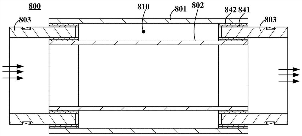
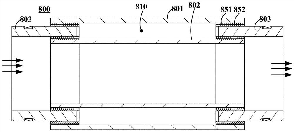
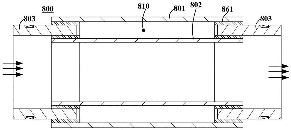
[0038] figure 1 It is a schematic structural diagram of a vacuum tube 800 according to an embodiment of the present invention. figure 2 It is a schematic structural diagram of a vacuum tube 800 according to another embodiment of the present invention. image 3 It is a schematic structural diagram of a vacuum tube 800 according to another embodiment of the present invention. The vacuum tube 800 of the present invention includes an outer tube 801, an inner tube 802 and an end sealing member 803, wherein the outer tube 801 is sleeved outside the inner tube 802, and is spaced apart from the inner tube 802; the end sealing member 803 is configured to be sandwiched Between the outer tube 801 and the inner tube 802 to seal the outer tube 801 and the inner tube 802 , and a vacuum chamber 810 is defined between the outer tube 801 , the inner tube 802 and the end seal 803 . The vacuum tube 800 of the present invention can reduce the convective heat transfer by evacuating between the two layers of tubes that are hermetically sealed; the outer tube 801 and the inner tube 802 are sealed and fixed by using the end seal 803 sandwiched between the two layers of tubes. The outer tube 801 and the inner tube 802 can always be kept at a certain distance, so that the structure of the entire vacuum tube 800 is stable, the independent appearance structure is maintained, and the vacuum chamber 810 can be kept in a stable vacuum state. The vacuum degree of the vacuum chamber 810 of the vacuum tube 800 of the present invention is 10 -1 -10 -3 Pa.
[0039] The outer tube 801 is made of metal tube; the inner tube 802 is made of metal tube; the end seal 803 is made of quartz glass. Both layers of tubes are metal tubes, which can stabilize the structure of the vacuum tube 800 . Preferably, both the outer tube 801 and the inner tube 802 are stainless steel tubes. It can be stainless steel tube with mirror surface or evaporation on the inner surface. For example, 304 stainless steel. The use of stainless steel tube can ensure the strength of the vacuum tube 800, the appearance is beautiful, the radiation heat transfer can be reduced, and the air leakage caused by corrosion and corrosion can be avoided at the same time. The end sealing member 803 is made of quartz glass, which has the characteristics of low thermal conductivity and low outgassing rate, which can solve the problem of heat bridge heat transfer of the vacuum tube 800 .
[0040] The thickness of the outer tube 801 and the thickness of the inner tube 802 may be the same or different. The thickness of the outer tube 801 is 1 mm-1.5 mm, for example, 1 mm, 1.2 mm, and 1.5 mm. The thickness of the inner tube 802 is 1 mm-1.5 mm, for example, 1 mm, 1.2 mm, 1.5 mm. The end seal 803 can be an annular member, and the length of the end seal 803 sandwiched between the outer tube 801 and the inner tube 802 is 10mm-15mm, such as 10mm, 12mm, 15mm. Through a lot of experimental research, it is preferable to limit the length range of the end seal 803 between the outer tube 801 and the inner tube 802 to 10mm-15mm, which can ensure that the end seal 803 is tightly sealed to the outer tube 801 and the inner tube 802 At the same time, it can prevent the volume of the vacuum chamber 810 from being reduced due to the excessively large end sealing member 803 , so that the thermal insulation effect of the vacuum insulator 100 is good. The distance between the outer tube 801 and the inner tube 802 is 0.5mm-20mm, for example, 0.5mm, 2mm, 5mm, 10mm, 15mm, 20mm. The distance between the outer tube 801 and the inner tube 802 is set to 0.5mm-20mm, which can meet different thermal insulation and product requirements. The inner diameter of the inner tube 802 is 3 to 5 times the distance between the outer tube 801 and the inner tube 802 .
[0041] like figure 1 As shown, in some embodiments, the end sealing member 803 is formed with a nickel-plated layer 841 on its inner and outer surfaces, respectively; a solder piece 842 is provided between the nickel-plated layer 841 and the outer tube 801 and the inner tube 802. The layer 841 and the solder piece 842 are welded to realize the sealing and fixing of the end seal 803 with the outer tube 801 and the inner tube 802 . Nickel-plated layers 841 are formed on the inner and outer surfaces of the end sealing member 803, respectively, and then the nickel-plated layers 841 and the solder pieces 842 are formed by the solder pieces 842 provided between the nickel-plated layer 841 and the outer tube 801 and the inner tube 802. Welding realizes the sealing and fixing of the end sealing member 803 with the outer tube 801 and the inner tube 802, so that the end sealing member 803 can be tightly sealed with the outer tube 801 and the inner tube 802, so as to avoid air leakage caused by loose sealing. The solder piece 842 can be selected from, for example, a silver-copper solder piece, Ag:Cu=72:28. The thickness of the nickel plating layer 841 is 1 μm-2 μm; the thickness of the solder piece 842 is 0.08 mm-0.12 mm, for example, 0.1 mm. The thickness of the nickel plating layer 841 is 1 μm-2 μm, which can meet the needs of adhesion and metal welding. The thickness of the solder sheet 842 is 0.08mm-0.12mm, which not only takes into account the welding strength, but also avoids heat conduction.
[0042] The preparation process of the vacuum tube 800 includes:
[0043] Nickel plating is performed on the end seal 803;
[0044] The end sealing member 803 is sandwiched between the outer tube 801 and the inner tube 802, and solder pieces 842 are respectively placed between the end sealing member 803 and the outer tube 801 and the inner tube 802;
[0045] The air between the outer tube 801 and the inner tube 802 is drawn out through the gap between the end seal 803 and the outer tube 801 and the inner tube 802;
[0046]The end seal 803 is welded and sealed with the outer tube 801 and the inner tube 802 .
[0047] The nickel plating treatment for the end sealing member 803 may adopt the method of nickel plating on quartz glass disclosed in the prior art. For example, quartz glass is pretreated first, and then electroless plating is performed with an electroless plating solution. Wherein, the pretreatment steps include: removing protective layer, degreasing, roughening, sensitizing, activating and heat treating; the chemical plating solution used is a mixed solution composed of nickel salt, reducing agent, buffer, complexing agent, etc.; The pretreated bare end seals 803 are electrolessly plated in the prepared electroless plating solution at a temperature of 80°C-90°C for a certain period of time, and then rinsed with deionized water to complete the end seals. Nickel plated on 803.
[0048] Welding, sealing and vacuuming are carried out in a vacuum furnace. Vacuum treatment is to evacuate to a degree of vacuum of 10 -1 -10 -3 Pa. The soldering temperature of the solder sealing process is 750°C to 850°C, for example, 800°C. After the welding and sealing treatment is completed, keep the temperature for 1min-2min, and then take the vacuum tube 800 out of the vacuum furnace.
[0049] like figure 2 As shown, in other embodiments, a metal sheet 851 is provided between the end sealing member 803 and the outer tube 801 and the inner tube 802 ; a glass frit paste is provided between the end sealing member 803 and the metal sheet 851 852 , the sealing and fixing of the end sealing member 803 , the outer tube 801 and the inner tube 802 are realized by melting the glass frit paste 852 and welding the metal sheet 851 . The glass frit paste 852 is used to fix the metal sheet 851 on the inner and outer surfaces of the end sealing member 803 respectively, and then the end sealing member 803 is sealed and fixed with the outer tube 801 and the inner tube 802 by welding the metal sheet 851, so that the end The sealing member 803 is tightly sealed with the outer tube 801 and the inner tube 802 to avoid air leakage caused by loose sealing. Metal strips may be used for the metal sheet 851 . The metal sheet 851 is made of materials that can compensate for the difference in thermal expansion coefficients between quartz glass and stainless steel tubes. The metal sheet 851 is a Kovar alloy, for example, a chromium-iron alloy, an iron-nickel-cobalt alloy, or the like.
[0050] The preparation process of the vacuum tube 800 includes:
[0051] Coating glass frit paste 852 on the metal sheet 851;
[0052] The metal sheets 851 are respectively attached to the inner and outer surfaces of the end seals 803, heated and melted to fix the metal sheets 851 on the inner and outer surfaces of the end seals 803, and then the end seals 803 are clamped to the outer tube 801 , between the inner tube 802;
[0053] The air between the outer tube 801 and the inner tube 802 is drawn out through the gap between the end seal 803 and the outer tube 801 and the inner tube 802;
[0054] The end seal 803 is welded and sealed with the outer tube 801 and the inner tube 802 .
[0055] The temperature of heating and melting is 440°C-460°C, which can melt the slurry, but cannot melt the glass.
[0056] Welding, sealing and vacuuming are carried out in a vacuum furnace. Vacuum treatment is to evacuate to a degree of vacuum of 10 -1 -10 -3 Pa. The soldering temperature of the solder sealing process is 750°C to 850°C, for example, 800°C. After the welding and sealing treatment is completed, keep the temperature for 1min-2min, and then take the vacuum tube 800 out of the vacuum furnace.
[0057] like image 3 As shown, in some other embodiments, a silicone layer 861 is provided between the end sealing member 803 and the outer tube 801 and the inner tube 802, and the end sealing member 803 and the outer tube 801, The sealing of the inner tube 802 is fixed. Using the silicone layer 861, the end sealing member 803 can be tightly sealed with the outer tube 801 and the inner tube 802, so as to avoid air leakage caused by loose sealing.
[0058] Silica gel is made of quick-drying silica gel, which has the strength properties of structural adhesive and the toughness of silica gel, and has good air tightness, which can be closely combined with quartz glass and stainless steel tubes. The thickness of the silicone layer 861 is 0.3mm-0.7mm, such as 0.3mm, 0.5mm, 0.7mm. The thickness of the silicone layer 861 is 0.3mm-0.7mm, which can take into account structural strength, toughness, heat insulation and air release.
[0059] Figure 4 It is a schematic structural diagram of a refrigerator 200 according to an embodiment of the present invention. Figure 5 It is a schematic structural diagram of a refrigerator 200 according to another embodiment of the present invention. Image 6 Yes image 3 A schematic cross-sectional view of the refrigerator 200 is shown. Figure 7 It is a schematic cross-sectional view of a vacuum insulator 100 according to an embodiment of the present invention. The refrigerator 200 of the present invention includes: one or more storage parts 201 , a refrigeration module 202 , and an air supply pipeline 300 . A corresponding storage space is defined in each storage portion 201 . The refrigeration module 202 is disposed separately from the one or more storage parts 201 and is configured to cool the air entering the refrigeration module 202 to form cooling capacity. One end of the air supply pipeline 300 is detachably connected to the refrigeration module 202, and the other end is connected to the storage part 201 for supplying cold energy into the storage part 201, wherein at least a part of the air supply pipeline 300 is the aforementioned Vacuum tube 800. The use of the vacuum tube 800 for air supply and cooling can avoid heat loss and condensation. In the refrigerator 200 of the present invention, the refrigeration module 202 and the storage part 201 are arranged separately, so that the storage part 201 does not need to make room for the refrigeration system, and the internal volume of the refrigerator 200 can be greatly increased; One or more identical or different storage parts 201 need to be freely matched, especially suitable for built-in refrigerators, which can greatly improve the utilization of space and improve user experience. E.g, figure 1 The illustrated refrigerator 200 includes a storage portion 201; figure 2 The illustrated refrigerator 200 includes two storage portions 201 . The number of the storage parts 201 may also be more than two, for example, three, four, and so on. Different storage parts 201 can be arranged in different positions and have different sizes, and the storage spaces can have different temperatures, which can meet different needs of users. In the present invention, "separately arranged" means that the main bodies are spaced apart by a certain distance, and the electrical circuits are connected through additional accessories. The cooling module 202 is provided with a cooling port, and one end of the air supply pipeline 300 is detachably connected to the cooling port of the cooling module 202 . The refrigeration module 202 may employ, for example, a compression refrigeration system, which includes an evaporator, a compressor, a cooling fan, and a condenser. like Image 6 As shown, the refrigeration module 202 includes an evaporator compartment 600 and a compressor compartment 700 . An evaporator is provided in the evaporator bin 600 . The compressor compartment 700 is arranged separately from the evaporator compartment 600, and is located behind the evaporator compartment 600. The compressor compartment 700 is provided with a compressor, a cooling fan and a condenser.
[0060] Below with Figure 4 Taking the refrigerator 200 shown as an example, the cooperation of the storage part 201 and the air supply pipeline 300, the storage part 201 and the refrigeration module 202 of the present invention will be described in detail.
[0061] The storage part 201 has a box body 210 and a door body 220, the box body 210 defines a storage space, and the door body 220 is disposed on the front side of the box body 210 to open and close the storage space. A drawer 280 is also provided in the box body 210 . The refrigerator 200 further includes a return air line 400 and a threading line 500 . The box body 210 is provided with an air supply installation port, a return air installation port and an electrical connection installation port. One end of the air supply pipeline 300 is fixed to the air supply installation port, and the other end is communicated with the cooling module 202 , so as to supply cooling energy from the cooling module 202 to the storage portion 201 . One end of the return air pipeline 400 is fixed to the return air installation port, and the other end is communicated with the refrigeration module 202, so that the air in the storage portion 201 flows into the refrigeration module 202 to be cooled. A power supply line is provided in the threading pipeline 500 , one end is introduced into the storage part 201 through the electrical connection installation port, and the other end is introduced into the refrigeration module 202 to realize the circuit connection between the storage part 201 and the refrigeration module 202 . The air supply line 300 and the return air line 400 use the aforementioned vacuum pipes 800 .
[0062] At least a part of the case 210 is the vacuum insulator 100 . Figure 7 It is a schematic structural diagram of a vacuum insulator 100 according to an embodiment of the present invention. The vacuum insulator 100 includes: a first plate 101 , a second plate 102 , and a sealing member 103 . The second plate 102 is spaced apart from the first plate 101 . The sealing member 103 is sandwiched between the first plate 101 and the second plate 102 to seal and fix the first plate 101 and the second plate 102 , and the first plate 101 , the second plate 102 and the sealing member 103 are defined between out of the vacuum chamber 110 . The vacuum degree of the vacuum chamber 110 of the vacuum insulator 100 is 10 -1 -10 -3 Pa. The first plate 101 constitutes at least a part of the outer shell 211 of the box body 210 , the second plate 102 constitutes at least a part of the inner shell 212 of the box body 210 , and the inner side of the second plate 102 away from the first plate 101 is the storage space of the box body 210 . The box body 210 is provided with an air supply installation port, a return air installation port and an electrical connection installation port on the vacuum insulator 100 , and the first board 101 and the second board 102 are provided with a heat insulating member 203 around the installation port. At least a part of the box body 210 of the refrigerator 200 of the present invention is the vacuum insulator 100, which can ensure the heat preservation effect of the refrigerator 200; the vacuum insulator 100 can reduce the convective heat transfer by vacuuming between the two layers of the hermetically sealed plates; The sealing member 103 is sandwiched between the first plate 101 and the second plate 102 to seal and fix the two layers of plates, so that the first plate 101 and the second plate 102 can always maintain a certain distance, so that the structure of the entire vacuum insulator 100 can be maintained. Stable and maintain a separate appearance structure.
[0063] The vacuum insulator 100 is used to form the box body 210, so that the wall thickness of the refrigerator 200 can be kept small and the heat preservation effect of the refrigerator 200 can be ensured. Greatly improve the utilization of space and improve user experience. The refrigerator 200 of the present invention can also be designed and used as a part of a smart home. The spaced arrangement of the second plate 102 relative to the first plate 101 may include two situations. One is that the main surfaces of the second plate 102 and the first plate 101 are substantially parallel to each other. When the vacuum insulator 100 is placed horizontally, its longitudinal cross-sectional view is as follows: Figure 7 shown. The first plate 101 and the second plate 102 are substantially flat plate-like structures, and the entire box 210 is formed by splicing a plurality of flat plate-like vacuum insulators 100 . One is that the first plate 101 is in the shape of a rectangular parallelepiped with an opening on one surface, and the second plate 102 is spaced and sleeved in the first plate 101 through the opening.
[0064]The first plate 101 is made of sheet metal; the second plate 102 is made of sheet metal; the sealing member 103 is made of quartz glass. Metal plates are used for both layers, which can stabilize the structure of the vacuum insulator 100 . Preferably, the first plate 101 is made of stainless steel plate, and the second plate 102 is made of stainless steel plate. It can be stainless steel plate with mirror surface or vapor deposition on the inner surface. For example, 304 stainless steel. The use of stainless steel plate can ensure the strength of the vacuum insulator 100, the appearance is beautiful, the radiation heat transfer can be reduced, and the air leakage caused by corrosion and corrosion can be avoided at the same time. The sealing member 103 is made of quartz glass, and the quartz glass has the characteristics of low thermal conductivity and low outgassing rate, which can solve the problem of heat bridge heat transfer of the vacuum insulator 100 . A sealing structure 104 is also formed between the first plate 101 and the second plate 102 and the sealing member 103 . Since the thermal expansion coefficients of the quartz glass and the stainless steel plate are 15 times different, the sealing structure 104 needs to be elastic and can be closely combined with the quartz glass and the stainless steel plate to ensure the tight connection between the quartz glass and the stainless steel plate. The sealing structure 104 may include a nickel-plated layer and a solder sheet; the upper and lower surfaces of the sealing member 103 are respectively formed with a nickel-plated layer, and a silver-copper solder sheet is arranged between the nickel-plated layer and the first board 101 and the second board 102, and the nickel-plated layer is , The silver copper solder sheet is welded to realize the sealing and fixing of the sealing member and the first board 101 and the second board 102 . The sealing structure 104 may also include Kovar alloy sheets and glass frit paste; Kovar alloy sheets are respectively provided between the sealing member 103 and the first plate 101 and the second plate 102, and between the sealing member 103 and the Kovar alloy sheets The glass frit paste is set, and the sealing member 103 and the first plate 101 and the second plate 102 are sealed and fixed by melting the glass frit paste and welding the Kovar alloy sheets. The sealing structure 104 may also include a silicone layer; a silicone layer is respectively provided between the sealing member 103 and the first plate 101 and the second plate 102, and the sealing member 103 and the first plate 101 and the second plate 102 are realized by bonding the silicone layer. Sealed and fixed. The vacuum insulator 100 may also include a plurality of supports 105 disposed within the vacuum chamber 110 configured to be secured with the first panel 101 and/or the second panel 102 so as to be between the first panel 101 and the second panel 102 Provide support. By arranging a plurality of support members 105 in the vacuum chamber 110, the first plate 101 and the second plate 102 can be supported, and the strength of the entire vacuum insulator 100 can be enhanced; The two plates 102 are fixed, so that the setting process of the support member 105 is simplified, and the manufacturing process of the entire vacuum insulator 100 is simplified. The support member 105 is preferably made of quartz glass or polytetrafluoroethylene, and is bonded and fixed to the first board 101 and/or the second board 102 by epoxy resin or silica gel.
[0065] Figure 8 Yes Figure 4 The illustrated schematic diagram of the cooperation between the storage part 201 of the refrigerator 200 and the air supply pipeline 300 is also Image 6 A partial enlarged view of section F in . refer to Figure 8 , the outside of the outlet end of the air supply pipeline 300 is provided with an air supply joint 341 , and the air supply joint 341 passes through the air supply installation port opened on the box body 210 . The fixing member 351 is threadedly engaged with the air supply joint 341 in the box body 210 , so as to fix the air supply pipeline 300 and the air supply joint 341 . The fixing of the air supply pipeline 300 and the box body 210 is realized by the cooperation of the air supply joint 341 and the fixing member 351 , the structure is ingenious, the installation is simple, and the stability is good. Specifically, the end seal 803 has a first section 831 between the outer tube 801 and the inner tube 802 , and a second section 832 beyond the ends of the outer tube 801 and the inner tube 802 . The air supply joint 341 is clamped and fixed with the second section 832 of the end sealing member 803 . The air supply joint 341 has a joint base 3411 and a joint protrusion 3412. The inner side of the joint base 3411 fits the outer shell 211. The end of the joint protrusion 3412 extends beyond the inner shell 212 and the outer side of the overhang part is provided with a thread with the fixing member 351. Structure corresponding thread structure. A rubber sealing ring 360 is also provided in the contact area between the air supply joint 341 and the box body 210 .
[0066] Figure 9 Yes Figure 4 The illustrated schematic diagram of the cooperation between the refrigeration module 202 of the refrigerator 200 and the air supply pipeline 300 is also Image 6 Partial enlarged view of section H in . refer to Figure 9 , the outside of the inlet end of the air supply pipeline 300 is provided with an air supply joint 342 , and the air supply joint 342 passes through the cooling port of the refrigeration module 202 . The fixing member 352 is threadedly engaged with the air supply joint 342 in the evaporator bin 600 , so as to fix the air supply pipeline 300 and the refrigeration module 202 . The fixing of the air supply pipeline 300 and the refrigeration module 202 is realized by the cooperation of the air supply joint 342 and the fixing member 352 , the structure is ingenious, the installation is simple, and the stability is good. Specifically, the end seal 803 has a first section 831 between the outer tube 801 and the inner tube 802 , and a second section 832 beyond the ends of the outer tube 801 and the inner tube 802 . The air supply joint 342 is clamped and fixed with the second section 832 of the end sealing member 803 . The air supply joint 342 has a joint base 3421 and a joint protrusion 3422. The inner side of the joint base 3421 is fitted with the cooling module 202. The end of the joint protrusion 3422 extends beyond the cooling port and is provided with a fixing member 352 on the outer side of the overhang. The thread structure corresponds to the thread structure. A rubber sealing ring 360 is also provided in the contact area between the air supply joint 342 and the cooling module 202 .
[0067] The vacuum tube 800 in the embodiment of the present invention can reduce convective heat transfer by evacuating between the two layers of tubes that are hermetically sealed; the outer tube 801 and the inner tube 802 are sealed by using the end seals 803 sandwiched between the two layers of tubes. By fixing, the outer tube 801 and the inner tube 802 can always maintain a certain distance, so that the structure of the entire vacuum tube 800 is stable, the independent appearance structure is maintained, and the vacuum chamber 810 can also maintain a stable vacuum state.
[0068] By now, those skilled in the art will recognize that, although various exemplary embodiments of the present invention have been illustrated and described in detail herein, the present invention may still be implemented in accordance with the present disclosure without departing from the spirit and scope of the present invention. The content directly determines or derives many other variations or modifications consistent with the principles of the invention. Accordingly, the scope of the present invention should be understood and deemed to cover all such other variations or modifications.

PUM

PropertyMeasurementUnit
Length10.0 ~ 15.0mm

Description & Claims & Application Information

We can also present the details of the Description, Claims and Application information to help users get a comprehensive understanding of the technical details of the patent, such as background art, summary of invention, brief description of drawings, description of embodiments, and other original content. On the other hand, users can also determine the specific scope of protection of the technology through the list of claims; as well as understand the changes in the life cycle of the technology with the presentation of the patent timeline. Login to view more.
Why Eureka
Try Eureka