
Unmanned aerial vehicle capturing equipment

A technology for capturing equipment and unmanned aerial vehicles, which is applied in the direction of offensive equipment, aircraft parts, defense devices, etc., and can solve the problems of small size of unmanned aerial vehicles, great influence on the landing position, and drug trafficking of unmanned aerial vehicles.

Pending Publication Date: 2021-07-06
王玉怀
View PDF0 Cites 4 Cited by
  • Summary
  • Abstract
  • Description
  • Claims
  • Application Information

AI Technical Summary

Problems solved by technology

But on the other hand, due to its small size, low flying airspace, and difficulty in radar detection, drones have become the main medium for various sabotage activities. Incidents of human-machine drug trafficking, smuggling and violent activities
At present, the police use anti-drone rope nets to capture hostile drones, but traditional capture devices cannot cut off the control of drones by hostile forces in time, giving hostile forces time to destroy criminal evidence
On the other hand, most of the traditional capture nets are launched from the ground, the capture accuracy is poor, and there is no protection for the core position of the hostile drone, which often causes damage to the data and items stored inside the drone when it falls to the ground
[0003] Traditional capture equipment usually uses a parachute for forced landing. This method of forced landing is slow, and the landing position is greatly affected by the wind direction, which is not conducive to the police's rapid acquisition of criminal evidence

Method used


Image

  • Unmanned aerial vehicle capturing equipment
  • Unmanned aerial vehicle capturing equipment
  • Unmanned aerial vehicle capturing equipment

Examples


Embodiment Construction

[0024] The following will clearly and completely describe the technical solutions in the embodiments of the present invention with reference to the accompanying drawings in the embodiments of the present invention. Obviously, the described embodiments are only some, not all, embodiments of the present invention. Based on the embodiments of the present invention, all other embodiments obtained by persons of ordinary skill in the art without making creative efforts belong to the protection scope of the present invention.

[0025] see Figure 1-8 , the present invention provides technical solutions:

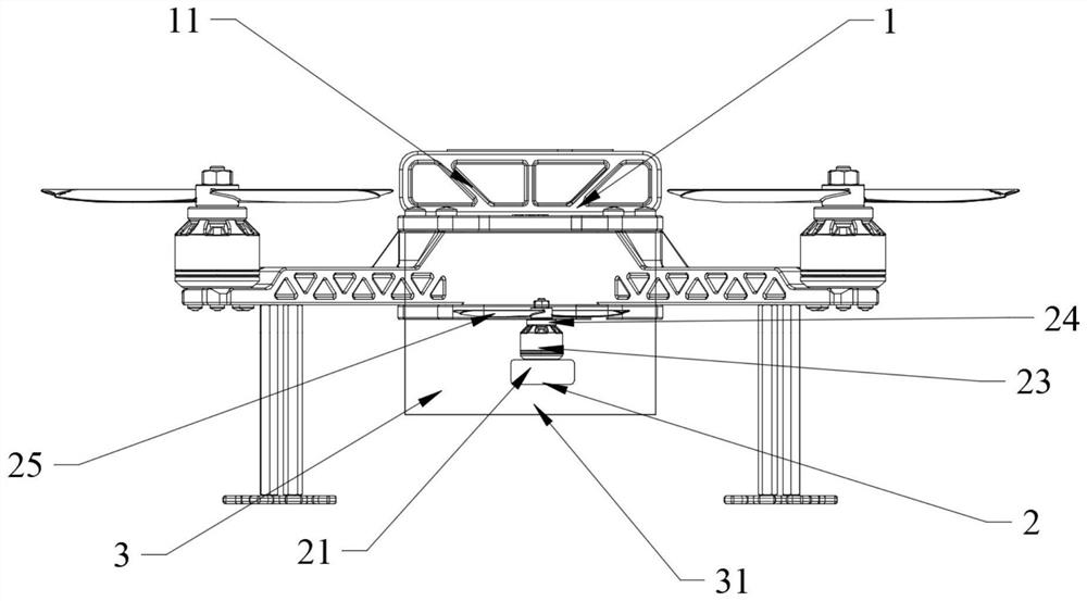
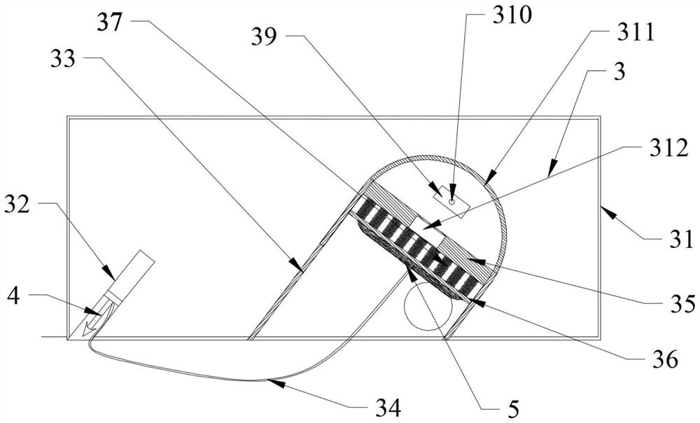
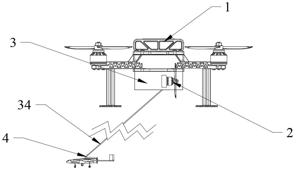
[0026] Such as Figure 1-5 As shown, the UAV capture device includes a carrier UAV 1, an adjustable rotor assembly 2, a launch assembly 3, a claw assembly 4, and a capture net assembly 5. The carrier UAV 1 includes a fuselage 11 and a detection radar , the detection radar is installed inside the fuselage 11, the launch assembly 2 is installed at the bottom of the fuselage 11, the ...


PUM


Abstract

The invention discloses unmanned aerial vehicle capturing equipment. The unmanned aerial vehicle capturing equipment comprises a carrying unmanned aerial vehicle, an adjustable rotor wing assembly, a launching assembly, a claw assembly and a capturing net assembly. The carrying unmanned aerial vehicle comprises a vehicle body and a detection radar, the detection radar is installed in the vehicle body, and the launching assembly is installed at the bottom of the vehicle body; the adjustable rotor wing assembly is fixedly connected with the side wall of the launching assembly, and the claw assembly and the capturing net assembly are installed in the launching assembly before launching. The adjustable rotor wing assembly can decelerate an enemy unmanned aerial vehicle, the claw assembly can rapidly and accurately hit the enemy unmanned aerial vehicle and build a capturing channel between the carrying unmanned aerial vehicle and the enemy unmanned aerial vehicle, and the capturing net assembly can shield communication signals of the unmanned aerial vehicle when capturing the unmanned aerial vehicle. Airflow output by an opening in the upper part of an outer net frame provides a guiding effect for falling of the unmanned aerial vehicle, so that the unmanned aerial vehicle rapidly lands in a designated area.

Description

technical field [0001] The invention relates to the technical field of unmanned aerial vehicles, in particular to an unmanned aerial vehicle capture device. Background technique [0002] In recent years, the demand for high technology in the field of military equipment has been increasing day by day, and the use of drones in the military has become more and more frequent. But on the other hand, due to its small size, low flying airspace, and difficulty in radar detection, drones have become the main medium for various sabotage activities. Human-machine drug trafficking, smuggling and violent activities. At present, the police mostly use anti-drone rope nets to capture hostile drones, but traditional capture devices cannot cut off the control of drones by hostile forces in time, giving hostile forces time to destroy criminal evidence. On the other hand, most of the traditional capture nets are launched from the ground, the capture accuracy is poor, and there is no protectio...

Claims


Application Information

Patent Timeline
IPC IPC(8): F41H11/02B64D1/02
CPCB64D1/02F41H11/02
Inventor 王玉怀
Owner 王玉怀
Learn More