Heat dissipation frame for new energy automobile battery management

A new energy vehicle and battery management technology, which is applied in the field of heat dissipation frame for battery management of new energy vehicles, can solve the problems of inability to adjust wind power, complicated operation, poor heat dissipation function, etc.

Pending Publication Date: 2021-07-06
韦龙印
View PDF0 Cites 7 Cited by
  • Summary
  • Abstract
  • Description
  • Claims
  • Application Information

AI Technical Summary

Problems solved by technology

[0004] In order to overcome the shortcomings of traditional battery heat dissipation equipment that cannot adjust the wind force, complex operation and poor heat dissipation function, the technical problem of the present invention is to provide a heat dissipation frame for new energy vehicle battery management that can realize wind force adjustment, simple operation and strong heat dissipation function

Method used


Image

  • Heat dissipation frame for new energy automobile battery management
  • Heat dissipation frame for new energy automobile battery management
  • Heat dissipation frame for new energy automobile battery management

Examples


Embodiment 1

[0030] A cooling frame for new energy vehicle battery management, such as Figure 1-Figure 3 Shown, comprise base plate 1, motor 2, propelling mechanism 3 and launching mechanism 4, base plate 1 upper front side is equipped with motor 2, base plate 1 is provided with propelling mechanism 3, and base plate 1 is provided with launching mechanism 4.

[0031] When people want to dissipate heat from the car battery, they can use this heat dissipation frame for new energy car battery management. First, the user puts the battery on the bottom plate 1, then injects cold water into the water launching mechanism 4, and starts the motor 2. The motor 2 drives the pushing mechanism 3 to run, and the pushing mechanism 3 cooperates with the water launching mechanism 4, so that cold water flows onto the battery through the water launching mechanism 4 to cool down the battery. Motor 2, the above actions all stop.

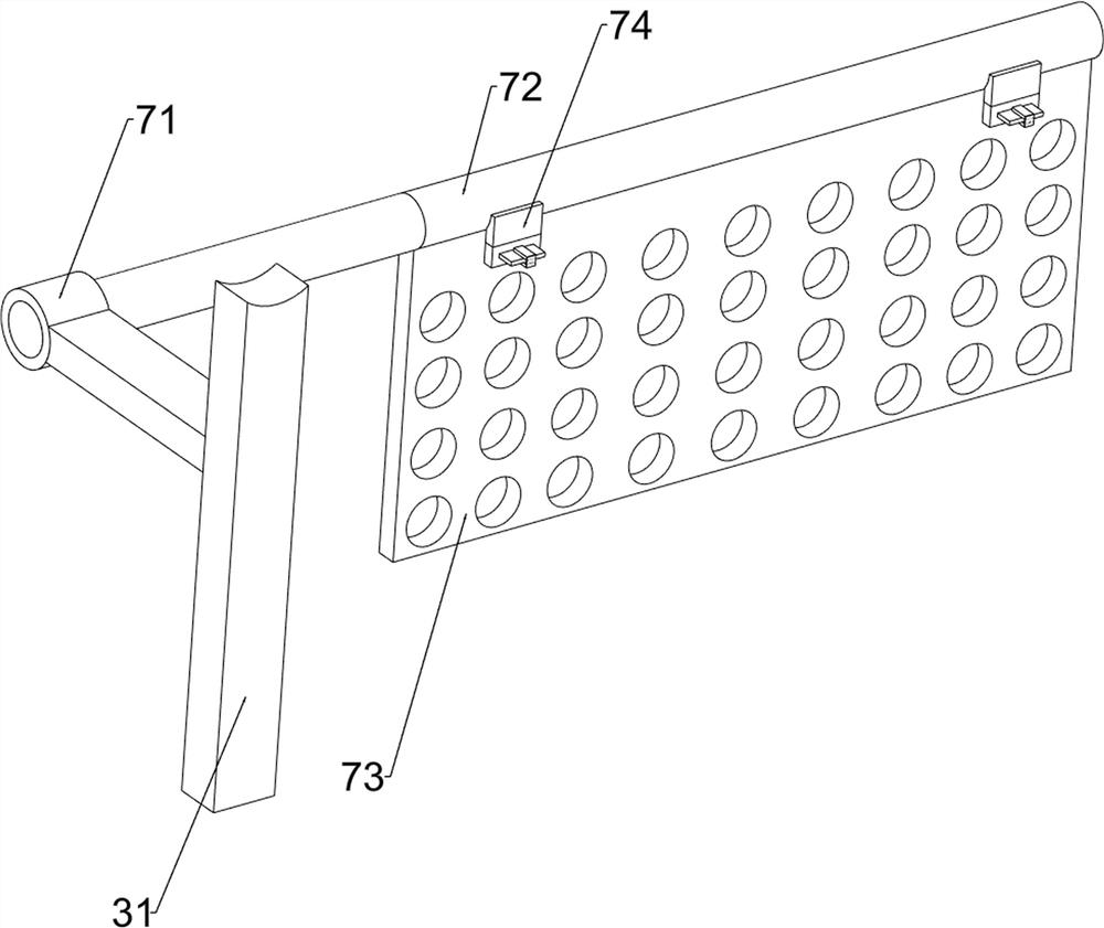
[0032] The pushing mechanism 3 includes a first support frame 31, a first supp...

Embodiment 2

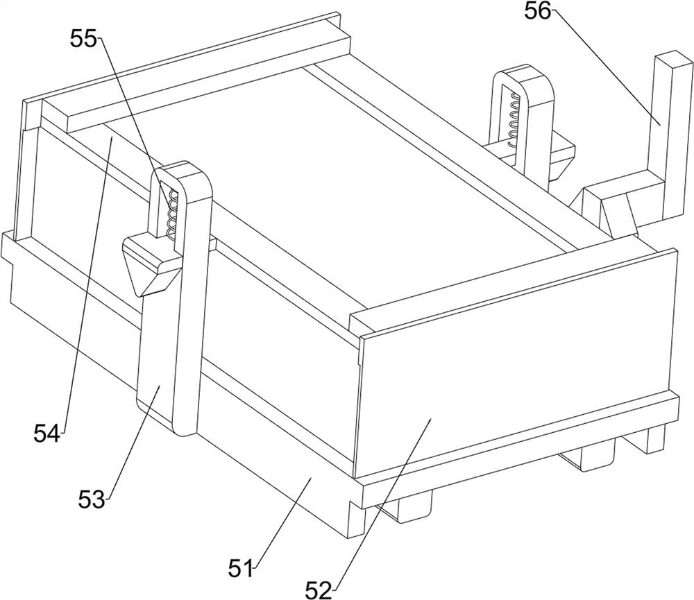
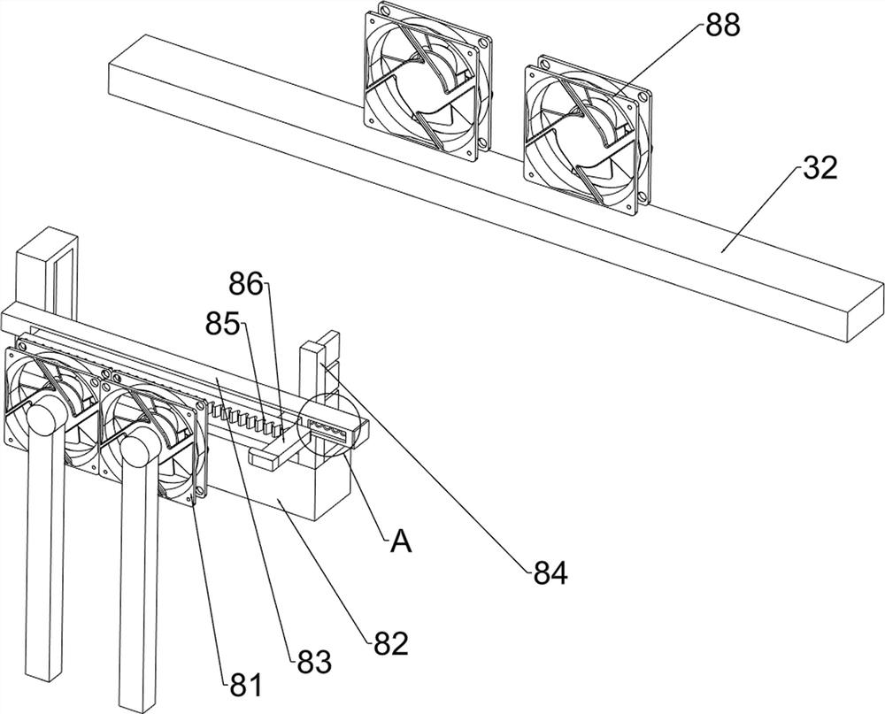
[0037] On the basis of Example 1, such as Figure 4-Figure 11 Shown, also comprise anti-vibration mechanism 5, be provided with anti-vibration mechanism 5 on the first support column 32, anti-vibration mechanism 5 comprises limit frame 51, baffle plate 52, second support column 53, second pressing plate 54, second spring 55 And the 3rd wedge-shaped block 56, the front side of the first support column 32 is provided with a spacer 51, the front and rear sides of the top of the spacer 51 are all provided with baffle plates 52, and the left and right sides of the spacer 51 are all provided with a second support column 53 A second pressure plate 54 is slidingly provided between the two second support columns 53, a second spring 55 is connected between the second pressure plate 54 and the second support column 53, and a third wedge block 56 is provided at the bottom of the push rod 34, The third wedge block 56 cooperates with the second pressing plate 54 .

[0038] When the push ro...


PUM


Abstract

The invention relates to a heat dissipation frame, in particular to a heat dissipation frame for new energy automobile battery management. The heat dissipation frame for new energy automobile battery management is capable of adjusting wind power, easy to operate and high in heat dissipation function. The heat dissipation frame for new energy automobile battery management comprises a bottom plate, a motor, a pushing mechanism, a water draining mechanism and the like. A motor is installed on the front side of the bottom plate, a pushing mechanism is arranged on the bottom plate, and a water draining mechanism is arranged on the bottom plate. The first conveying assembly drives the lead screw to rotate reversely, the lead screw drives the push rod to move forwards to the original position, and the effect that the lead screw drives the push rod to move is achieved; and the first pressing plate is separated from the water pipe, so that cold water flows onto the battery through the water pipe and cools the battery, and the battery cooling effect is achieved.

Description

technical field [0001] The invention relates to a heat dissipation frame, in particular to a heat dissipation frame for new energy vehicle battery management. Background technique [0002] With the continuous development of social economy and the continuous progress and innovation of science and technology, new energy vehicles also appear. New energy vehicles do not need petroleum resources and can run on electric energy alone, which is energy-saving and environmentally friendly. Although there are cooling devices in traditional new energy vehicles, most of the cooling devices are simple heat sinks and fans. The heat dissipation effect is average, and the heat dissipation method cannot be adjusted. The vacuum function will also affect the heat dissipation effect in the long run, and the heat dissipation method cannot be adjusted according to the heat generation of the battery, resulting in a waste of energy. [0003] To this end, we have designed a heat dissipation frame fo...

Claims


Application Information

Patent Timeline
Patent Type & Authority Applications(China)
IPC IPC(8): H01M10/613H01M10/625H01M10/6568H01M10/6563H01M50/244H01M50/242H01M50/249H01M50/289B08B1/00B08B5/02B08B13/00
CPCB08B1/002B08B5/02B08B13/00H01M10/613H01M10/625H01M10/6563H01M10/6568Y02E60/10
Inventor 韦龙印
Owner 韦龙印
Why Eureka
Try Eureka