Vacuum suction crane for transferring metal smelting rolled steel plates

A technology of metal smelting and suction hoisting machine, which is applied in the direction of cranes, transportation and packaging, and load hanging components. The effect of improving the utilization rate

Pending Publication Date: 2021-12-28
安庆市宏信金属制品有限公司
View PDF5 Cites 0 Cited by
  • Summary
  • Abstract
  • Description
  • Claims
  • Application Information

AI Technical Summary

Problems solved by technology

[0003] However, the existing vacuum lifters use cable ties to fix the connecting wires. When the cable ties are fixed too tightly, the wires will be damaged and the service life of the wires will be shortened, thereby causing poor contact to the normal use of the vacuum lifter. The impact of the cable tie is not easy to replace, and it is easy to break the cable tie when it is used for a long time, which increases the cost and usage of the cable tie replacement; at the same time, the existing vacuum suction cup is not easy to adjust the extension and shortening, resulting in vacuum suction There are limitations in the use of the vacuum suction machine, which reduces the utilization rate of the vacuum suction machine; and when the steel plate is moved, the transfer of the steel plate is realized through the movement of the electric hoist body, but the movement of the electric hoist body will cause damage to the inner wall of the boom body. Collision, which increases the damage of the electric hoist body and shortens the service life of the electric hoist body

Method used


Image

  • Vacuum suction crane for transferring metal smelting rolled steel plates
  • Vacuum suction crane for transferring metal smelting rolled steel plates
  • Vacuum suction crane for transferring metal smelting rolled steel plates

Examples


Embodiment Construction

[0024] The following will clearly and completely describe the technical solutions in the embodiments of the present invention with reference to the accompanying drawings in the embodiments of the present invention. Obviously, the described embodiments are only some, not all, embodiments of the present invention. Based on the embodiments of the present invention, all other embodiments obtained by persons of ordinary skill in the art without making creative efforts belong to the protection scope of the present invention.

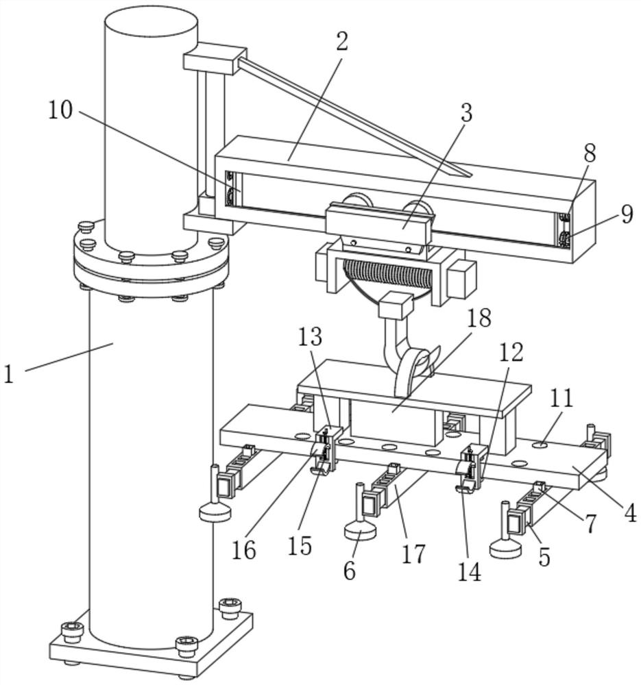
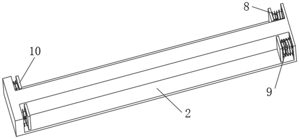
[0025] see figure 1 , the present invention provides a technical solution: a vacuum suction hoist for metal smelting and rolling steel plate transfer, including a vacuum suction hoist body 1, a boom body 2 is movably installed on the right side of the vacuum suction hoist body 1, and a boom body 2. The movable connection with the vacuum lifting machine body 1 realizes the movement of the boom body 2, thereby achieving the effect of transferring the steel plate...


PUM


Abstract

The invention discloses a vacuum suction crane for transferring metal smelting rolled steel plates, and relates to the technical field of steel plate transferring, in particular to the vacuum suction crane for transferring the metal smelting rolled steel plates. The vacuum suction crane comprises a vacuum suction crane body, a suspension arm body is movably mounted on the right side of the vacuum suction crane body, an electric hoist body is movably installed on the front face of the suspension arm body, and a vacuum suction cup support is movably installed at the lower end of the electric hoist body. According to the vacuum suction crane for transferring the metal smelting rolled steel plates, through cooperation of the suspension arm body, the electric hoist body, a telescopic rod, a first spring and a buffer plate, the movement effect of the buffer plate is achieved through compression and rebounding of the telescopic rod and the first spring, the problem that the electric hoist body collides with the inner wall of the suspension arm body during movement is effectively solved, the anti-collision effect on the electric hoist body is achieved through movement of the buffer plate, damage to the electric hoist body is reduced, and the service life of the electric hoist body is prolonged.

Description

technical field [0001] The invention relates to the technical field of steel plate transfer, in particular to a vacuum suction hoist for metal smelting and rolling steel plate transfer. Background technique [0002] The steel plate is a flat steel material that is poured with molten steel and pressed after cooling. It is flat and rectangular, and can be rolled directly or cut from a wide steel strip. The steel plate is indispensable in the production and processing of the steel plate. In the transfer process, a vacuum suction hoist is needed to realize the transfer of the steel plate, and the vacuum suction hoist (commonly known as the elephant nose vacuum hoist) is a fast, safe and convenient automatic equipment. It uses the principle of vacuum adsorption to convert the vacuum pump or vacuum As a vacuum source, the blower generates a vacuum at the end of the suction cup, thereby firmly sucking up various workpieces, and transporting the workpieces to the designated position...

Claims


Application Information

Patent Timeline
Patent Type & Authority Applications(China)
IPC IPC(8): B66C1/02B66C23/16B66C15/04B66C13/08
CPCB66C1/025B66C23/166B66C15/04B66C13/08
Inventor 孔书香孔书远孔向阳
Owner 安庆市宏信金属制品有限公司
Why Eureka
Try Eureka