
Transmission and distribution cooperative automatic voltage control method considering voltage regulation demand of power distribution network

A technology of automatic voltage and control methods, applied in the field of electric power, can solve problems such as abnormal operation of user electrical equipment, insufficient capacity of reactive power compensation configuration, and ineffective voltage control effect, etc.

Active Publication Date: 2021-07-06
YIBIN POWER SUPPLY COMPANY STATE GRID SICHUAN ELECTRIC POWER +1
View PDF4 Cites 0 Cited by
  • Summary
  • Abstract
  • Description
  • Claims
  • Application Information

AI Technical Summary

Problems solved by technology

[0003] In the power system, the distribution network is at the end of the entire system, and its voltage quality is directly related to whether the user's electrical equipment can run stably. When the system provides a voltage lower than the rated voltage of the user's electrical equipment, the user's electrical equipment will not operate normally. On the contrary, when the voltage provided by the system is higher than the rated voltage of the user's electrical equipment, the service life of the user's electrical equipment will be shortened, and even the electrical equipment will be damaged.
The main causes of distribution network voltage problems are small line cross-sectional area, large power supply radius, insufficient reactive power compensation configuration capacity, aging equipment, etc., and the voltage regulation method is to install a single reactive power compensation device on the line. Unified control and high cost, the effect of voltage control is not obvious

Method used


Image

  • Transmission and distribution cooperative automatic voltage control method considering voltage regulation demand of power distribution network

Examples


Embodiment Construction

[0014] The present invention will be described in detail below in conjunction with the accompanying drawings and specific embodiments, where the schematic embodiments and descriptions of the present invention are used to explain the present invention, but not to limit the present invention.

[0015] A transmission and distribution coordinated automatic voltage control method considering the voltage regulation requirements of the distribution network proposed by the present invention includes the following steps:

[0016] (1) Set the automatic voltage control period as T c ;

[0017] (2) In each automatic voltage control cycle T c When it arrives, obtain the transmission network model, bus voltage measurement, switch status, and transformer active power and reactive power from the energy management system (EMS), and read the mth bus B in the transmission network substation m current voltage of Voltage upper limit and voltage lower limit Where m∈[1, M], M is the total nu...


PUM


Abstract

The invention provides a transmission and distribution cooperative automatic voltage control method considering the voltage regulation demand of a power distribution network. The method comprises the following steps: acquiring a transmission and distribution network model and real-time data to construct a transmission and distribution integrated power grid model; for all load node voltages of feeder lines under 10kV buses of the transformer substation, judging whether the load node voltages are out of limit or not, calculating the rate that the load node voltages are close to or out of the upper limit and the rate that the load node voltages are close to or out of the lower limit under the feeder lines; if the load node voltage approaching or exceeding the upper limit rate under a certain feeder line is greater than the threshold value approaching or exceeding the upper limit rate, updating the voltage upper limit of the corresponding 10kV bus; if the load node voltage under a certain feeder line is close to or out of the lower limit rate and is larger than the threshold value close to or out of the lower limit rate, updating the corresponding 10kV bus voltage lower limit; if the voltage of the 10kV bus exceeds the upper limit, downshifting the tap of the substation where the 10kV bus is located or switching the capacitive reactance device; and if the voltage of the 10kV bus exceeds the lower limit, selecting the tap of the transformer substation where the 10kV bus is located to upshift or the capacitive reactance device is switched.

Description

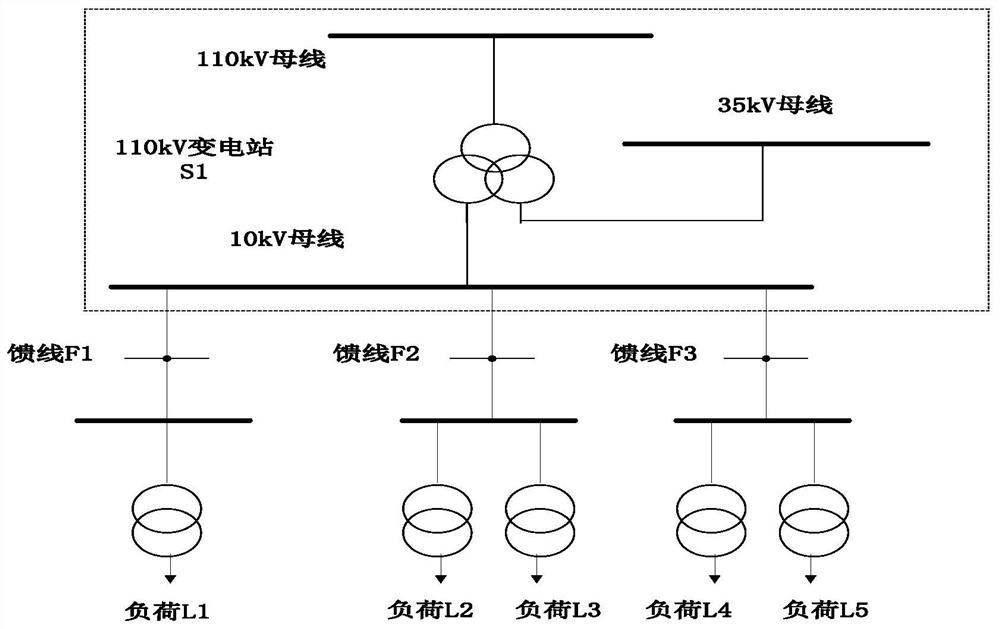
technical field [0001] The invention relates to the field of electric power, in particular to an automatic voltage control method for transmission and distribution coordination considering the voltage regulation requirements of a distribution network. Background technique [0002] Automatic voltage control (hereinafter referred to as AVC, Automatic Voltage Control) system is an important means to achieve safe (improved voltage stability margin), economical (reduced network loss), and high-quality (improved voltage qualification rate) operation of the transmission network. The AVC system architecture is based on the grid energy management system (EMS), which can use the real-time operation data of the transmission grid to scientifically make the best reactive power and voltage adjustment scheme from the perspective of overall optimization of the transmission grid, and automatically send it to power plants, substations and subordinates The power grid dispatching organization e...

Claims


Application Information

Patent Timeline
IPC IPC(8): H02J3/12H02J3/16
CPCH02J3/12H02J3/16H02J2203/10H02J2203/20Y02E40/30
Inventor 谢江陈旭锋杨磊陈柏杉李兴利龚雪张欣陈城周锐王鹏汤磊
Owner YIBIN POWER SUPPLY COMPANY STATE GRID SICHUAN ELECTRIC POWER
Learn More