Endoscope cutting anastomat

A stapler and endoscope technology, applied in the field of staplers, can solve the problems of inconvenient clamping, narrow scope of application, misoperation of staplers, etc., and achieve the effects of prolonging service life, wide application range and ensuring stability

Active Publication Date: 2021-07-09
SUZHOU FRANKENMAN MEDICAL EQUIP
View PDF10 Cites 0 Cited by
  • Summary
  • Abstract
  • Description
  • Claims
  • Application Information

AI Technical Summary

Problems solved by technology

Surgical staplers such as endoscopic cutting staplers can be adapted to enter narrow passages. They have slender shafts and chucks. The cutting knife is perpendicular to the direction of nail output. Through the cooperation of wedges, when the knife head cuts forward, the nails emerge in the vertical direction. However, the existing staplers often have the following problems in the process of use: 1. The existing staplers are often only suitable for a certain length of cutting and suturing operations, making the scope of application narrow, which is not conducive to large-scale promotion and use 2. The existing stapler has poor stability between the driving devices during the driving process, resulting in a shortened service life of the stapler; 3. The existing stapler is inconvenient to rotate during the clamping process, resulting in inconvenient clamping, thereby not It is conducive to the smooth progress of the operation; 4. Most of the existing staplers are single-row sutures, resulting in poor suture effect and affecting the healing effect; 5. The existing staplers are prone to accidental touches during use, which can easily lead to Operational errors affect the success of the operation

Method used


Image

  • Endoscope cutting anastomat
  • Endoscope cutting anastomat
  • Endoscope cutting anastomat

Examples


Embodiment Construction

[0029] In order to make the technical means, creative features, goals and effects achieved by the present invention easy to understand, the present invention will be further described below in conjunction with specific embodiments.

[0030]In the description of the present invention, it should be noted that the terms "upper", "lower", "inner", "outer", "front end", "rear end", "both ends", "one end", "another end" The orientation or positional relationship indicated by etc. is based on the orientation or positional relationship shown in the drawings, and is only for the convenience of describing the present invention and simplifying the description, rather than indicating or implying that the referred device or element must have a specific orientation, use a specific Azimuth configuration and operation, therefore, should not be construed as limiting the invention. In addition, the terms "first" and "second" are used for descriptive purposes only, and should not be understood a...


PUM


Abstract

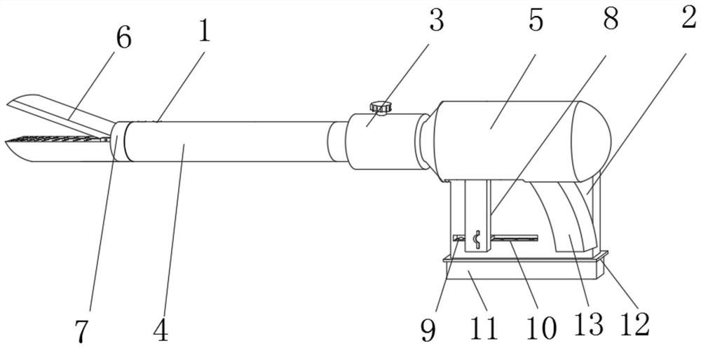
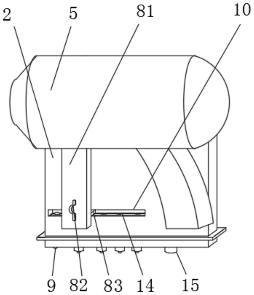
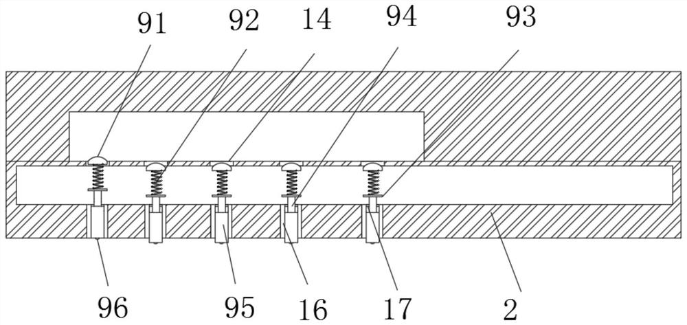
The invention discloses an endoscope cutting anastomat. The endoscope cutting anastomat comprises a handle part, a steering device is fixedly mounted at the left end of the handle piece; the left end of the steering device is fixedly connected with a thin shaft piece, and the left end of the thin shaft piece is provided with an adapter piece; a clamping piece is arranged at the left end of the adapter piece; the rear end of the handle piece is fixedly connected with a base plate; a first sliding groove is formed in the left portion of the front end of the base plate, a plurality of limiting devices are arranged in the base plate, and an operation device is slidably connected into the first sliding groove. According to the endoscope cutting anastomat, cutting and suturing of various lengths can be achieved through the arrangement of the limiting device and the operating device, and large-area application and popularization are facilitated; besides, a limiting ring and a limiting sliding rail can guarantee the gear meshing stability in the driving process, and the service life of the anastomat is prolonged; the steering device can adjust and control the clamping angle of the clamping piece; and multi-row sewing and different sewing heights, the sewing effect can be improved; in addition, the protection shell can avoid the phenomenon of mistaken touch.

Description

technical field [0001] The invention relates to the technical field of staplers, in particular to an endoscopic cutting stapler. Background technique [0002] As an alternative to traditional manual suturing equipment used in medicine, staplers are favored and respected by clinical surgeons at home and abroad. Surgical staplers such as endoscopic cutting staplers can be adapted to enter narrow passages. They have slender shafts and chucks. The cutting knife is perpendicular to the direction of nail output. Through the cooperation of wedges, when the knife head cuts forward, the nails emerge in the vertical direction. However, the existing staplers often have the following problems in the process of use: 1. The existing staplers are often only suitable for a certain length of cutting and suturing operations, making the scope of application narrow, which is not conducive to large-scale promotion and use 2. The existing stapler has poor stability between the driving devices du...

Claims


Application Information

Patent Timeline
IPC IPC(8): A61B17/072
CPCA61B17/07207A61B2017/07285
Inventor 陆坚曹新东
Owner SUZHOU FRANKENMAN MEDICAL EQUIP
Why Eureka
Try Eureka