Plasma cleaning machine

A technology of a plasma cleaning machine and a cleaning machine, which is applied in the field of cleaning machines, can solve the problems that the cleaning machine is easy to dump, and achieve the effects of saving space, reducing the possibility of dumping, and reducing the possibility

Inactive Publication Date: 2021-07-09
深圳市众铭安科技有限公司
View PDF5 Cites 0 Cited by
  • Summary
  • Abstract
  • Description
  • Claims
  • Application Information

AI Technical Summary

Problems solved by technology

[0005] In order to improve the problem that the cleaning machine is easy to fall when

Method used


Image

  • Plasma cleaning machine
  • Plasma cleaning machine
  • Plasma cleaning machine

Examples


Embodiment Construction

[0031] Contraction below Figure 1-4 Further detailed description of the present application.

[0032] The present application example discloses a plasma cleaning machine.

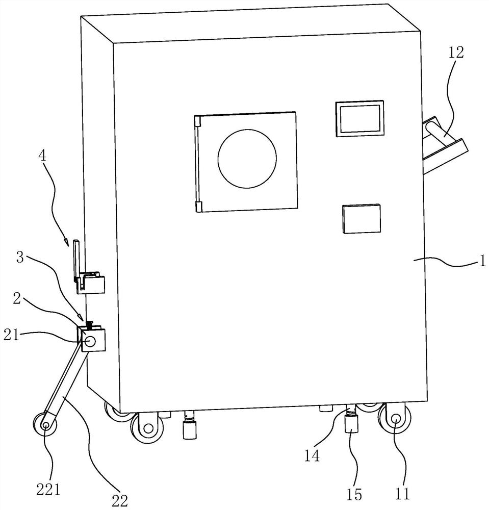
[0033] Such as figure 1 As shown, the plasma cleaning machine includes a cleaning machine body 1, and four moving wheel 11 are mounted in the lower surface of the cleaning machine body 1. A vertical side surface of the cleaning machine body 1 is fixedly coupled to the handle 12, when the cleaning machine body 1 is required, the staff holds the handle 12 forward the cleaning machine body 1.

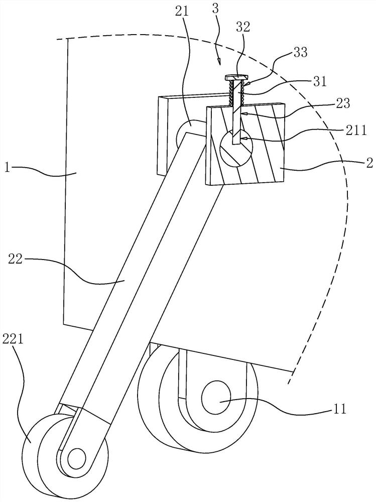
[0034] Such as figure 1 with figure 2 As shown, the cleaning machine body 1 is fixed to one side of the handle 12, and a pair of support plates 2 are provided, and the rod 21 is provided between the support plates 2, and the rotating rod 21 is rotated to the support plate 2. The rotating rod 21 is fixed to the support rod 22, and the support rod 22 is attached to one end of the rotary rod 21, and the support wheel 221 is ro...


PUM


Abstract

The invention relates to the field of cleaning machines, in particular to a plasma cleaning machine which comprises a cleaning machine body. A plurality of moving wheels are installed on the lower surface of the cleaning machine body, a supporting rod is connected to one vertical side face of the cleaning machine body, and a supporting wheel in contact with the ground is installed on the side, away from the cleaning machine body, of the supporting rod. The plasma cleaning machine has the effect of reducing the probability of toppling in the forward movement process of the cleaning machine body.

Description

Technical field [0001] The present application relates to the field of cleaning machines, in particular, involving a plasma cleaning machine. Background technique [0002] At present, when cleaning the liquid crystal glass, a plasma cleaning machine is required, the plasma cleaning machine is an effect that the plasma does not achieve the conventional cleaning method. [0003] A liquid crystal glass plasma cleaning machine is disclosed, and a body, the inner cavity of the body is provided with a native, and the cleaning chamber is distributed over the bottom position. The cleaning room cavity is provided with several uniformly distributed partitions. The electrode plates are provided at both ends and lower ends of the partition, and the cleaning chamber is rotated by the hinge, and the liquid crystal glass is placed in the cleaning chamber for cleaning. Four moving wheels are provided at the bottom of the body such that the cleaning machine is easy to move. [0004] In response t...

Claims


Application Information

Patent Timeline
IPC IPC(8): B08B7/00B08B11/00B08B13/00
CPCB08B7/00B08B11/00B08B13/00
Inventor 康众罗双泉
Owner 深圳市众铭安科技有限公司
Why Eureka
Try Eureka