Printing machine with adjustable roll shaft

A printing machine and adjustable technology, applied in printing machines, rotary printing machines, printing, etc., can solve problems such as inability to adapt to different raw material thicknesses, affect printing quality and speed, product color fading or color mixing, etc., to improve printing efficiency and use performance, reduce heat loss, and reduce energy consumption

Inactive Publication Date: 2021-07-09
李宝新
View PDF0 Cites 0 Cited by
  • Summary
  • Abstract
  • Description
  • Claims
  • Application Information

AI Technical Summary

Problems solved by technology

[0005] Aiming at the deficiencies of the prior art, the present invention provides a printing machine with adjustable rollers, which solves the problem that traditional printing machines mostly print and dye through rollers, and these rollers are not adjustable and cannot adapt to the thickness of different raw materials. Large limitations affect printing efficiency, and the dyes are not completely dry, resulting in color fading or color mixing of some products after printing, which seriously affects printing quality and speed, and reduces the problem of performance

Method used


Image

  • Printing machine with adjustable roll shaft
  • Printing machine with adjustable roll shaft
  • Printing machine with adjustable roll shaft

Examples


Embodiment example 1

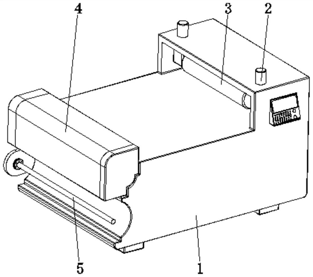
[0030] see Figure 1-6 , the present invention provides a technical solution: a printing machine with adjustable rollers, including a body 1, a lifting mechanism 2, a roller body 3, a drying device 4, and a receiving shaft 5, and the lifting mechanism 2 is arranged on the top of the body 1 On one side, the roller body 3 is arranged inside the body 1 and is connected with the working end of the lifting mechanism 2, the drying device 4 is arranged on the top of the body 1 and one end away from the roller body 3, and the receiving shaft 5 is arranged on the side of the body 1 The bottom of the surface is located below the drying device 4;

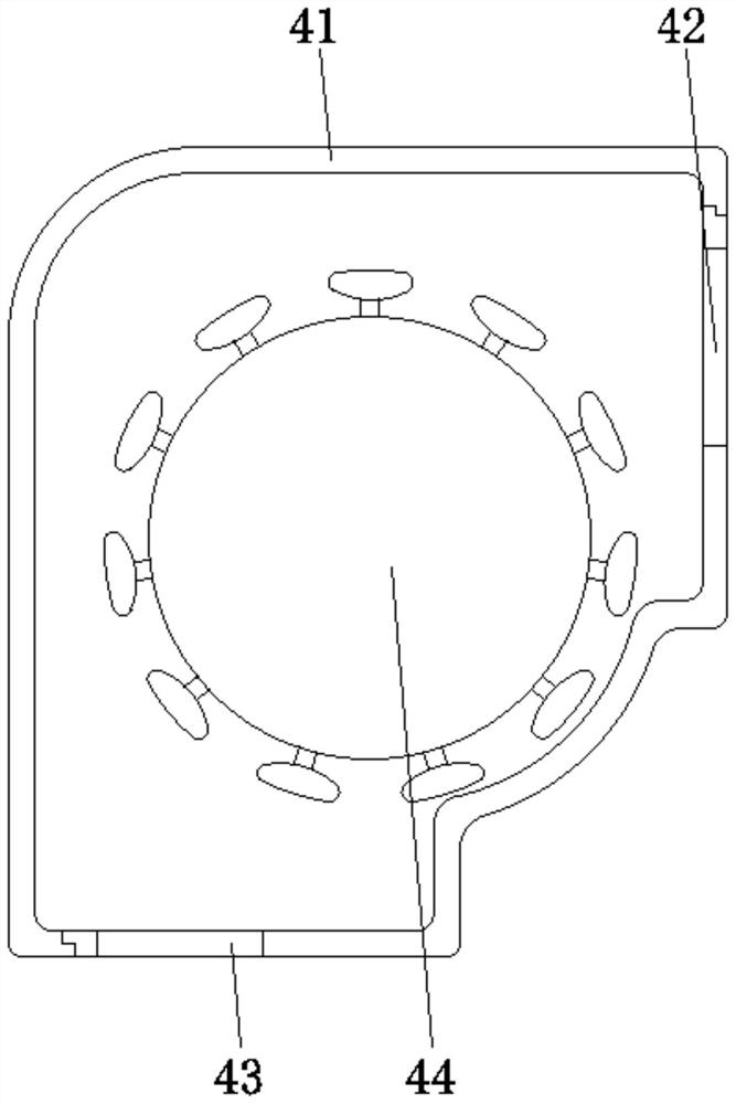
[0031] The drying device 4 is provided with a casing 41, an inlet 42, an outlet 43, and a heating device 44. The casing 41 is fixed on the top side of the body 1, and the inlet 42 and the outlet 43 are respectively set on the top side and the bottom side of the surface of the casing 41. The heating device 44 is set inside the shell 41, which ...

Embodiment example 2

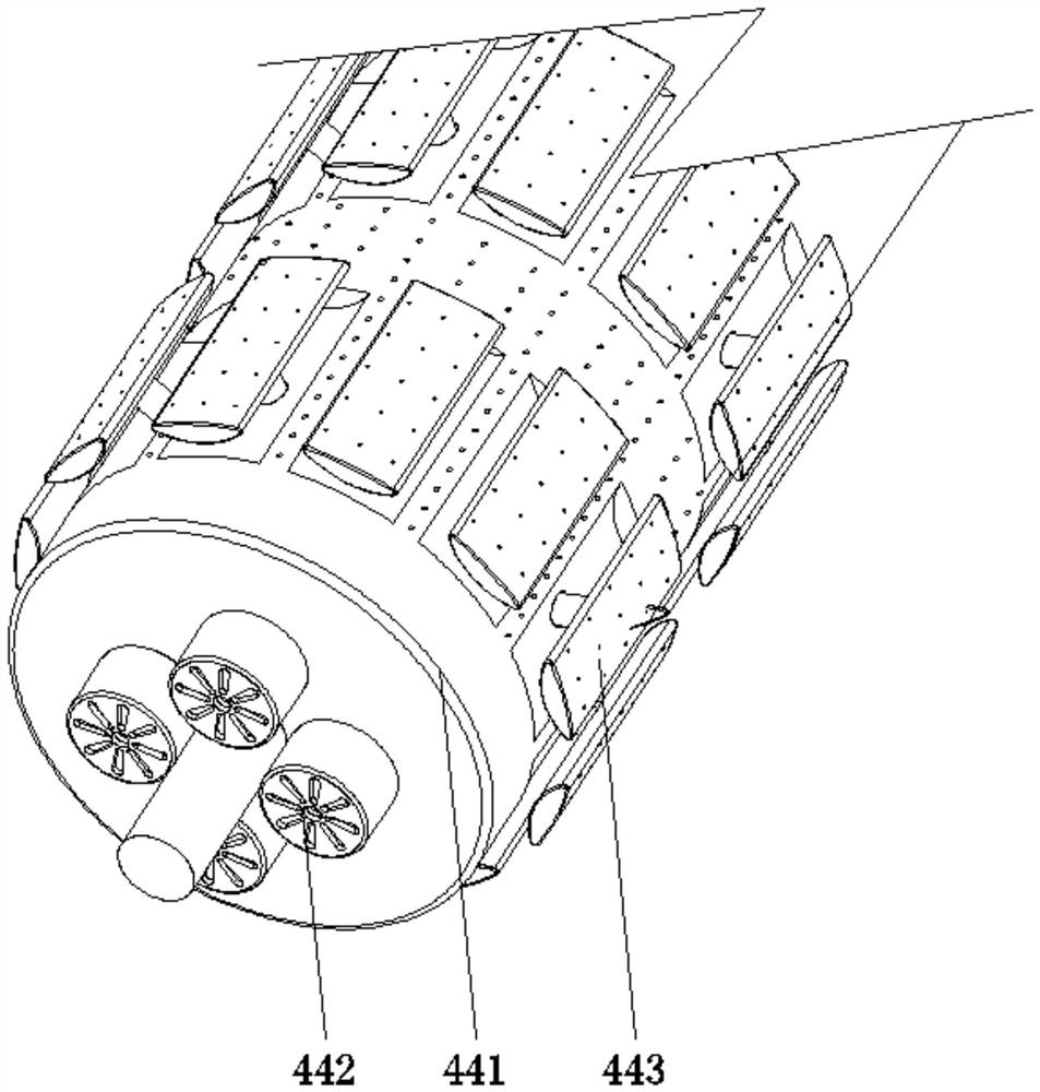
[0035] The heat dissipation device 443 is provided with a cavity 4431, a heat conduction device 4432, and an elastic airbag 4433. The cavity 4431 is set inside the roller device 441, and the heat conduction device 4432 is arranged on the surface of the roller body 4411 and is slidably connected with the roller body 4411. The airbag 4433 is set inside the cavity 4431 and fixedly connected to the end of the heat conduction device 4432. When the printed raw material passes through the heat dissipation device 443, the close contact between the raw material and the heat conduction device 4432 is used, and the heat transfer principle is used to control the dye. Carry out heating and drying, and at the same time, the raw material will press the heat conduction device 4432 downward, so that after the elastic airbag 4433 is compressed, combined with the control of the gas flow direction by the one-way valve, the internal hot gas will be ejected to the raw material, and then heated again,...

Embodiment example 3

[0038] By setting the roller device 441, the hot air cavity 4412, the cavity 4431, the heat conduction device 4432, and the elastic air bag 4433, when the printed material is in contact with the heat conduction device 4432, it is pressed, so that the hot air inside the elastic air bag 4433 is sprayed out, and the dye is heated. Drying, at the same time, with the rotation of the drum device 441, the heat conduction device 4432 away from the raw material has no pressure effect, and is lifted up after the volume of the elastic air bag 4433 expands. The hot air absorption is conducive to spraying hot air to the dye after being pressed again, so as to recycle the heat and reduce the waste of heat. The whole structure is connected together, which is safe and reliable, and improves the performance.

[0039] When in use, at first one end of the raw material is bypassed from the top of the surface of the heating device 44 in the casing 41 and connected to the receiving shaft 5. At this ...


PUM


Abstract

The invention discloses a printing machine with an adjustable roll shaft, and relates to the technical field of printing equipment. The printing machine comprises a machine body, a lifting mechanism, a roller body, a drying device and a material receiving shaft. The lifting mechanism is arranged on one side of the top of the machine body, the roller body is arranged in the machine body and connected with the working end of the lifting mechanism in a matched mode, the drying device is arranged at the end, away from the roller body, of the top of the machine body, and the material receiving shaft is arranged at the bottom of the surface of the machine body and located below the drying device. A shell is fixed to one side of the top of the machine body, an inlet and an outlet are correspondingly formed in one side of the top of the surface of the shell and one side of the bottom of the surface of the shell, and a heating device is arranged in the shell. According to the printing machine with the adjustable roll shaft, the purposes of rapid drying and heat recycling are achieved, the structure is reasonable and simple, use is convenient, dye can be rapidly dried in time, heat is recycled, heat loss is reduced, energy consumption is low, and the printing efficiency and the use performance are improved.

Description

technical field [0001] The invention relates to the technical field of printing equipment, in particular to a printing machine with adjustable roller shafts. Background technique [0002] With the continuous advancement of science and technology, the printing industry has also developed rapidly. A printing machine is a device for printing patterns on fabrics. It is suitable for printing on a variety of materials. After modification, the application range of the printing machine is wider, and it is no longer limited to paper printing. The printing machine can generally be divided into: thermal transfer printing machine, digital printing machine, flat screen printing machine, rotary screen printing machine and There are several types of walking printing machines. The application range of printing machines is more extensive, no longer limited to paper printing, the domestic gift market has reached 9.8 billion, and it has become a popular trend of gifts. Print your own photos...

Claims


Application Information

Patent Timeline
Patent Type & Authority Applications(China)
IPC IPC(8): B41F17/00B41F23/04
CPCB41F17/003B41F23/04
Inventor 李宝新
Owner 李宝新
Why Eureka
Try Eureka