
Control method and device of rotary drilling rig and rotary drilling rig

A technology of a rotary drilling rig and a control method, which is applied in the field of rotary drilling rigs, control methods and devices of rotary drilling rigs, can solve problems such as sticking, which is easy to occur, so as to reduce dependence on experience, improve drilling efficiency, and prevent sticking. Effect

Pending Publication Date: 2021-07-09
ZOOMLION HEAVY IND CO LTD
View PDF18 Cites 0 Cited by
  • Summary
  • Abstract
  • Description
  • Claims
  • Application Information

AI Technical Summary

Problems solved by technology

[0004] The purpose of the embodiment of the present invention is to provide a control method and device for a rotary drilling rig and the rotary drilling rig, which solves the problem of facing the operation of the rotary drilling rig in the prior art. Drill sticking is easy to occur when the medium changes, and it depends on the experience of the operator to match the appropriate power output gear. When the real-time speed of the power head or drill pipe changes to the preset critical speed, according to the preset critical speed and power head The gear corresponding relationship of the torque output value or the gear of the preset oil cylinder pressure output value, adjust the power head torque of the rotary drilling rig or the output of the oil cylinder pressure to match the drilling of the current working medium, reducing the drilling process. Relying on the operator's experience in the process can effectively prevent the drill bit from getting stuck and match the appropriate power output to improve drilling efficiency

Method used


Image

  • Control method and device of rotary drilling rig and rotary drilling rig
  • Control method and device of rotary drilling rig and rotary drilling rig
  • Control method and device of rotary drilling rig and rotary drilling rig

Examples


Embodiment Construction

[0024] Specific embodiments of the present invention will be described in detail below in conjunction with the accompanying drawings. It should be understood that the specific embodiments described here are only used to illustrate and explain the present invention, and are not intended to limit the present invention.

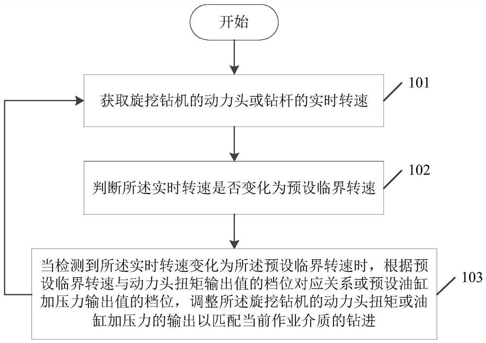
[0025] figure 1 It is a schematic flowchart of a control method for a rotary drilling rig provided by an embodiment of the present invention. Such as figure 1 As shown, the method includes the following steps:

[0026] Step 101, obtaining the real-time rotational speed of the power head or the drill pipe of the rotary drilling rig;

[0027] Step 102, judging whether the real-time speed has changed to a preset critical speed;

[0028] Step 103, when it is detected that the real-time rotational speed has changed to the preset critical rotational speed, adjust the preset critical rotational speed according to the gear corresponding relationship between the pres...


PUM


Abstract

The invention relates to the field of engineering machinery, discloses a control method and device of a rotary drilling rig and the rotary drilling rig, and solves the problems that the rotary drilling rig is easy to drill when an operation medium changes and a proper power output gear is matched by depending on the experience of an operator in the prior art. The method comprises the following steps: acquiring a real-time rotating speed of a power head or a drill rod of the rotary drilling rig; judging whether the real-time rotating speed is changed into a preset critical rotating speed or not; and when detecting that the real-time rotating speed is changed into the preset critical rotating speed, adjusting the output of the torque of the power head or the pressure of an oil cylinder of the rotary drilling rig according to a gear corresponding relation between the preset critical rotating speed and a torque output value of the power head or a gear of a preset pressure output value of the oil cylinder so as to match the drilling of the current operation medium. The embodiment of the invention is suitable for the drilling process of the rotary drilling rig.

Description

technical field [0001] The invention relates to the field of engineering machinery, in particular to a control method and device for a rotary drilling rig and the rotary drilling rig. Background technique [0002] During the drilling process of rotary drilling rigs, the geological conditions often change, from soft soil to hard rock, and the strength of the working medium varies widely. In the prior art, the torque output of the power head of the rotary drilling rig can be adaptively adjusted according to the change of the load, and matched with the appropriate power of the main engine. When the drilling geology is soft soil or sandy soil, because the strength of the working medium is not strong, the load adaptive matching will not cause drastic changes in the torque and speed of the power head, and can drill smoothly. However, when the drilling geology changes from soft soil to hard rock or the type of rock to be drilled changes, the strength of the working medium will cha...

Claims


Application Information

Patent Timeline
IPC IPC(8): E21B44/04E21B44/06
CPCE21B44/04E21B44/06
Inventor 刘宏亮陈玉磊何欢
Owner ZOOMLION HEAVY IND CO LTD
Features
  • Generate Ideas
  • Intellectual Property
  • Life Sciences
  • Materials
  • Tech Scout
  • Unparalleled Data Quality
  • Higher Quality Content
  • 60% Fewer Hallucinations
Learn More