
Detection method and detection system of electronic compass

An electronic compass and detection system technology, applied in the field of detection, can solve the problems of magnetization damage of components, waste of manpower and time, etc., and achieve the effect of simple assembly, quick use and short detection time

Pending Publication Date: 2021-07-09
HANGZHOU QIFEI INTELLIGENT TECH CO LTD
View PDF6 Cites 0 Cited by
  • Summary
  • Abstract
  • Description
  • Claims
  • Application Information

AI Technical Summary

Problems solved by technology

At present, most of the factory tests of the electronic compass are only to verify the accuracy of the electronic compass. However, during the compass assembly process, there may be reverse installation of the front and back of the circuit board, or the magnetization of the components may be damaged due to the use of magnetic tools during the assembly process. The situation occurs; the currently commonly used detection scheme is to install it on a specific device (such as a drone) for detection, and then analyze the collected data after actual measurement. This method is a waste of manpower and time

Method used


Image

  • Detection method and detection system of electronic compass
  • Detection method and detection system of electronic compass
  • Detection method and detection system of electronic compass

Examples


Embodiment 1

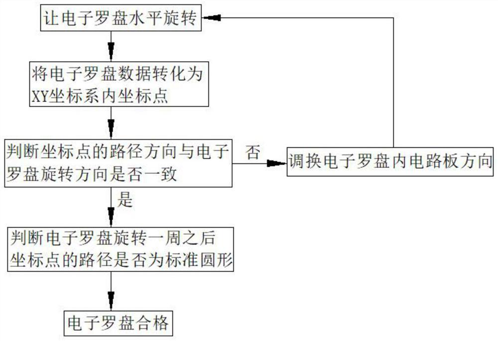
[0063] Such as figure 1 Shown, a kind of detection method of electronic compass comprises:

[0064] (1) Let the electronic compass rotate horizontally,

[0065] (2) Convert the electromagnetic field modulus generated by the electronic compass into coordinate points in the XY plane;

[0066] (3) Whether the path direction of the coordinate point is consistent with the horizontal rotation of the electronic compass to judge whether the circuit board installation of the electronic compass is correct;

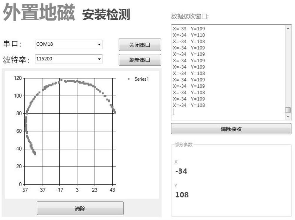
[0067] (4) Let the electronic compass rotate one circle horizontally, and judge whether the electronic compass is damaged by magnetization according to the proximity of the coordinate point path to the standard circle;

[0068] (5) The electronic compass that satisfies the detection of steps (3) and (4) at the same time is a qualified product.

[0069] Wherein, the detection of the step (3) is performed with priority relative to the detection of the step (4).

[0070] In this em...

Embodiment 2

[0072] Such as figure 1 As shown, different from the above embodiments, in this embodiment, the detection of the step (3) is performed simultaneously with the detection of the step (4).

[0073] At the same time, regardless of whether there is a problem with the circuit board, it can quickly detect whether the electronic compass is damaged by magnetization and whether the magnetic field value is normal; when it is confirmed that the electronic compass is normal, the test can be passed on the spot. Repair speed.

Embodiment 3

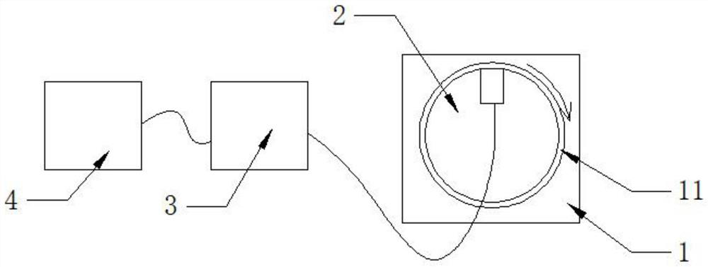
[0075] Such as figure 1 , figure 2 As shown, in this embodiment, a detection system of an electronic compass is provided, including:


PUM


Abstract

The invention discloses a detection method and a detection system of an electronic compass. The detection method comprises the following steps: (1) horizontally rotating the electronic compass; (2) converting an electromagnetic field module value generated by the electronic compass into coordinate points in an XY plane; (3) judging whether the circuit board of the electronic compass is correctly installed according to whether the path direction of the coordinate point is consistent with the horizontal rotation of the electronic compass; (4) horizontally rotating the electronic compass for a circle, and judging whether the electronic compass is magnetized and damaged according to the closeness degree of the coordinate point path and the standard circle; and (5) determining that the electronic compass which simultaneously meets the detection conditions in the step (3) and the step (4) is a qualified product. The invention further discloses a hardware detection system matched with the detection method. According to the detection method, the assembled electronic compasses can be detected one by one to determine whether the products are qualified or not, the detection time is short, the operation is not complicated, and detection personnel can complete detection basically without training.

Description

technical field [0001] The invention relates to the detection field, in particular to a detection system of an electronic compass. Background technique [0002] Electronic compass, also known as digital compass, has been widely used in aviation, aerospace, robotics, navigation, vehicle autonomous navigation and other fields as a navigation instrument or attitude sensor in modern technical conditions. At present, most of the factory tests of the electronic compass are only to verify the accuracy of the electronic compass. However, during the compass assembly process, there may be reverse installation of the front and back of the circuit board, or the magnetization of the components may be damaged due to the use of magnetic tools during the assembly process. The situation occurs; currently, the commonly used detection scheme is to install it on a specific device (such as a drone) for detection, and then analyze the collected data after actual measurement. This method is a wast...

Claims


Application Information

Patent Timeline
IPC IPC(8): G01C17/38
CPCG01C17/38
Inventor 陈玮宇唐勇赵浩轶
Owner HANGZHOU QIFEI INTELLIGENT TECH CO LTD
Learn More