
Optical path device of fiber-optic gyroscope and optical fiber coiling method

A fiber-optic gyroscope and fiber-optic coiling technology, which can be used in measurement devices, Sagnac effect gyroscopes, gyroscopes/steering sensing devices, etc., and can solve problems such as performance deterioration of gyroscopes

Pending Publication Date: 2021-07-09
北京凌微光电科技有限公司
View PDF8 Cites 1 Cited by
  • Summary
  • Abstract
  • Description
  • Claims
  • Application Information

AI Technical Summary

Problems solved by technology

[0004] In view of this, the purpose of this application is to provide an optical path device and an optical fiber coiling method for a fiber optic gyroscope, through which the optical path device for a fiber optic gyroscope and the optical fiber coiling improve the optical path symmetry of the fiber optic gyroscope. Problem with gyro performance degradation due to improper handling of device pigtails during assembly

Method used


Image

  • Optical path device of fiber-optic gyroscope and optical fiber coiling method
  • Optical path device of fiber-optic gyroscope and optical fiber coiling method
  • Optical path device of fiber-optic gyroscope and optical fiber coiling method

Examples


Embodiment Construction

[0034] The purpose, technical solutions, and advantages of the present application will become more apparent from the drawings in the present application embodiment, and the technical solutions in the present application will be clear and completely described, and it should be understood that The figure only shows the purposes of illustration and description, and is not intended to limit the scope of protection of the present application. In addition, it should be understood that the schematic drawings are not drawn according to the physical proportion. The flowcharts used in this application show the operation implemented in accordance with some embodiments of the present application. It should be understood that the operation of the flowchart can be implemented in order, and the steps without logical contextual relationships can reverse the order or simultaneously. Furthermore, in the art of the present application, one or more other operations can be added to the flowchart, or ...


PUM


Abstract

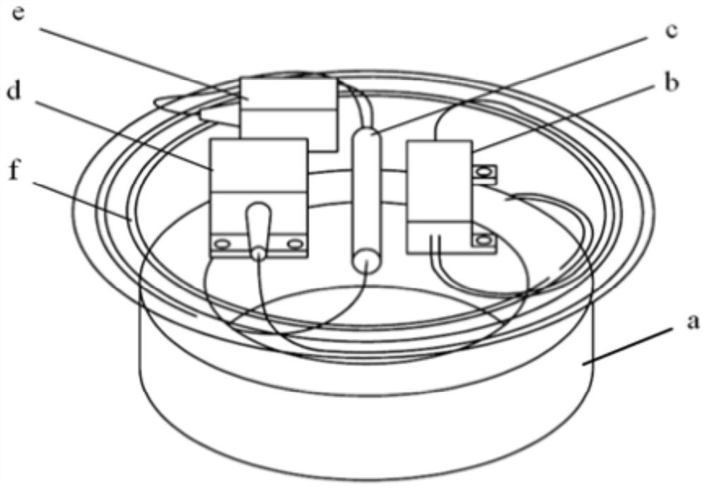
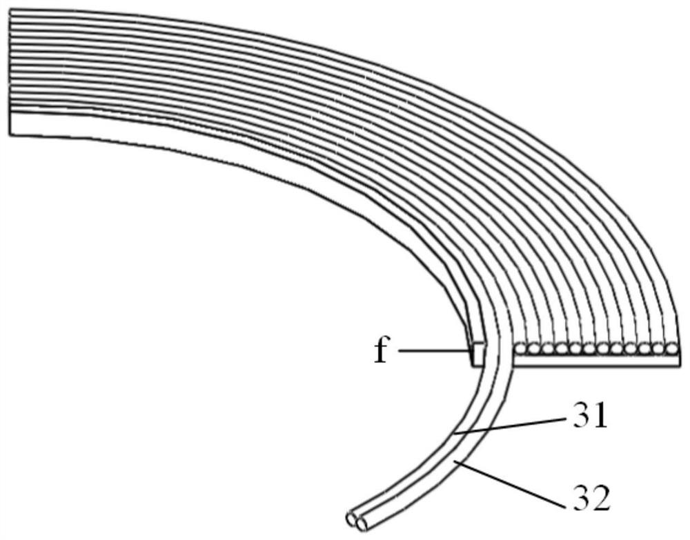
The invention provides an optical path device of an optical fiber gyroscope and an optical fiber coiling method, the optical path device comprises an optical fiber ring, a waveguide, a coupler, a detector, a light source and a middle hollow annular fiber coiling structure, the optical fiber ring and the annular fiber coiling structure are arranged in parallel; the waveguide, the coupler, the detector and the light source are all arranged at the middle hollow position of the annular fiber coiling structure; and tail fibers among the optical fiber ring, the waveguide, the coupler, the detector and the light source are coiled on the annular fiber coiling structure. Therefore, through the optical path device of the fiber-optic gyroscope and the device tail fiber single-layer symmetric coiling method for improving the optical path symmetry of the fiber-optic gyroscope through optical fiber coiling, the problem of gyroscope performance deterioration caused by improper treatment of the device tail fiber during assembly of the fiber-optic gyroscope is solved.

Description

Technical field [0001] The present application relates to the technical field of fiber optic gyro, and more particularly to an optical path device and a fiber disk winding method of fiber optic gyro. Background technique [0002] As a new inertial instrument, the fiber optic gyroscope is widely used in the field of missiles, airplanes, ships and vehicles due to their precision, power consumption, quality and other aspects. With the wide application of fiber optic gyro, the number of fiber optic gyro is increasing, and performance requirements are getting higher and higher. As the foundation of SAGNAC effect, optical path performance directly determines the gyro performance. The optical path is composed of the optical device and its tailib through the welding connection. With the diversification of demand, the fibergroup performance, functional requirements are also diversified, and the product technology status needs to change often, resulting in randomness of optical paths. In o...

Claims


Application Information

Patent Timeline
IPC IPC(8): G01C19/72G01C25/00
CPCG01C19/721G01C25/00
Inventor 李志宏刘言邱小锋王长文闵春华
Owner 北京凌微光电科技有限公司
Learn More