Axis alignment method for direct coupling of polarization maintaining optical fiber ring terminal and integrated optical chip

A polarization-maintaining fiber ring and integrated optics technology, which is used in surveying, mapping and navigation, measuring devices, instruments, etc., can solve the problems of low coupling efficiency, difficult handling of polarization-maintaining fibers and Y-waveguide chips, and low axis alignment accuracy, etc. Accuracy and speed, repeatability and universality, precise control of effects

Active Publication Date: 2020-06-02
BEIHANG UNIV
View PDF14 Cites 1 Cited by
  • Summary
  • Abstract
  • Description
  • Claims
  • Application Information

AI Technical Summary

Problems solved by technology

[0004] The difficulty of direct coupling is that the surface of the fiber terminal of the polished fiber ring needs to be protected, which makes the alignment between the polarization maintaining fiber and the Y waveguide chip and the optimization of optical power monitoring more difficult. Optical power monitoring can be carried out by building an optical system similar to a fiber optic gyroscope Monitoring, the alignment between the polarization maintaining fiber and the Y-waveguide chip is difficult to deal with. At present, there are not many direct coupling technology solutions. Usually, the geometric end face of the fiber terminal is barely aligned or the complex imaging system is used for online observation. The above two methods It will bring problems of low alignment accuracy (coupling polarization crosstalk higher than 30dB requires an alignment angle error of less than 0.5°), low coupling efficiency, and difficult system implementation

Method used


Image

  • Axis alignment method for direct coupling of polarization maintaining optical fiber ring terminal and integrated optical chip
  • Axis alignment method for direct coupling of polarization maintaining optical fiber ring terminal and integrated optical chip
  • Axis alignment method for direct coupling of polarization maintaining optical fiber ring terminal and integrated optical chip

Examples


Embodiment 1

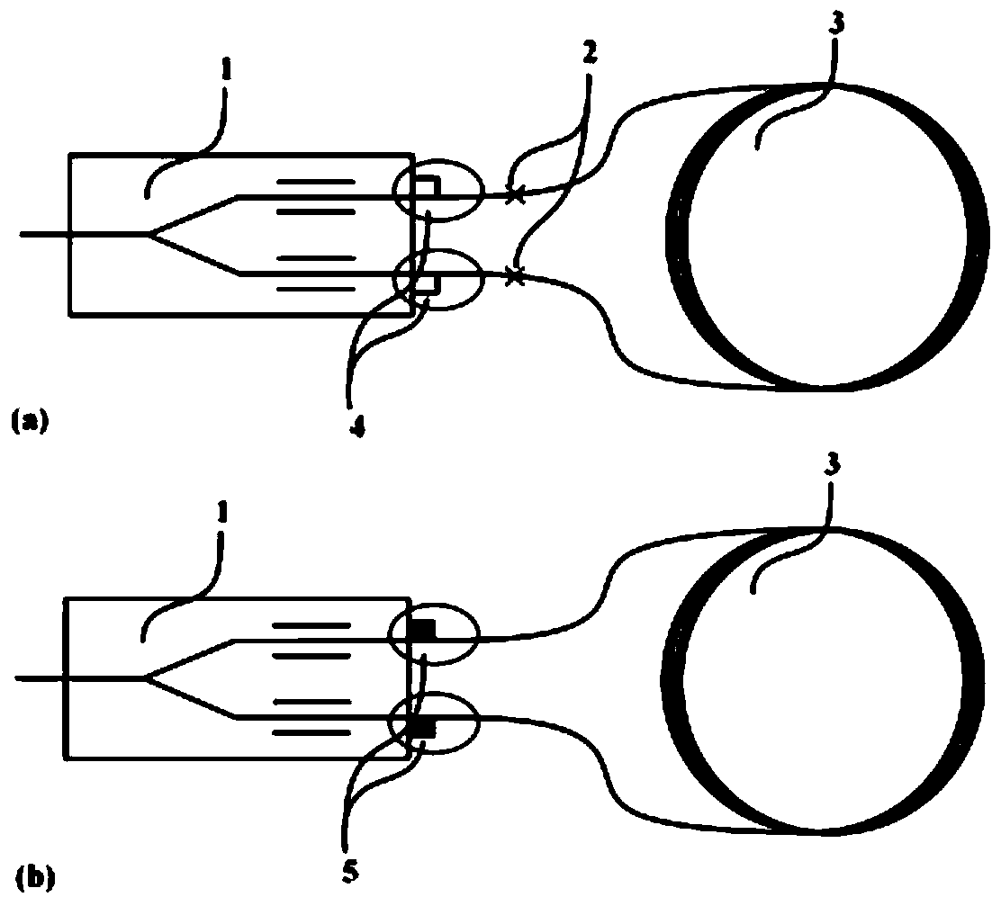
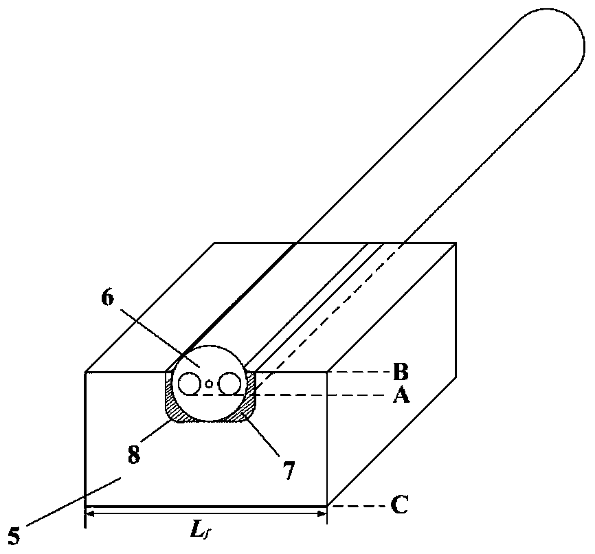
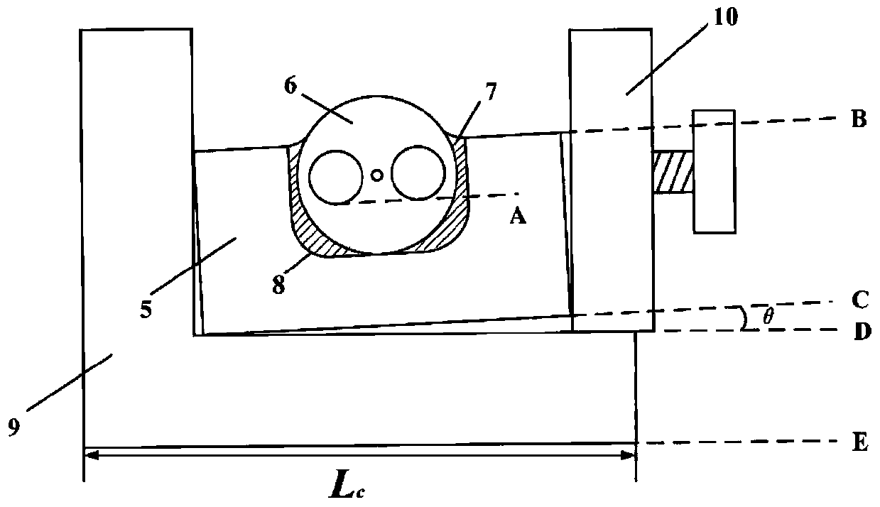
[0039] After the pigtail fiber of the polarization-maintaining optical fiber ring 3 is removed from the coating layer, it is bonded with the U-shaped optical fiber groove 8 through the curing glue 7 and then ground to produce the polarization-maintaining optical fiber ring terminal 5, the A line and the B line of the polarization-maintaining optical fiber ring terminal 5 The angle between the lines is less than 0.2°. Line A is the cat’s-eye baseline of the polarization-maintaining fiber, representing a polarization state of the beam in the polarization-maintaining fiber. Line B is the baseline on the upper surface of the polarization-maintaining fiber ring terminal 5, such as figure 2 shown. in length L f During the assembly process of the polarization-maintaining optical fiber ring terminal 5 and the coupling jig 9 with a diameter of 1-1.5mm, since the clamping device 10 did not compact the bottom surface of the polarization-maintaining optical fiber ring terminal 5 and the ...


PUM


Abstract

The invention discloses an axis alignment method for direct coupling of a polarization maintaining optical fiber ring terminal and an integrated optical chip. Direct coupling of the polarization maintaining optical fiber ring terminal and the integrated optical modulator chip is achieved through two coupling processes of end face observation of the polarization maintaining optical fiber ring terminal and clamping of a coupling clamp. By means of the technical scheme, the problem that the performance of the fiber-optic gyroscope is degraded due to the fact that additional optical nonreciprocalerrors are generated due to the melting point in the fiber-optic gyroscope is solved, the precision and speed of coupling angle error identification are improved, and accurate control over the coupling angle of the polarization axis is achieved.

Description

technical field [0001] The invention belongs to the technical field of coupling and packaging of integrated optical chips, and in particular relates to an axis alignment method for direct coupling of a polarization-maintaining optical fiber ring terminal and an integrated optical modulator chip. Background technique [0002] In the manufacturing process of the fiber optic gyroscope, the connection of the fiber optic ring and the multifunctional integrated optical modulator can be realized by the method of pigtail fusion. The fusion splicing process requires a certain length of pigtail, and the coiling of the pigtail will affect the performance of the fiber optic gyroscope in some applications. For high-precision fiber optic gyroscopes, improving performance is the main appeal of this type of gyroscope. An important means of improving performance is to minimize the fiber optic ring. The non-reciprocal error in the combination of multi-functional integrated optical modulator (...

Claims


Application Information

Patent Timeline
Patent Type & Authority Applications(China)
IPC IPC(8): G01C19/72
CPCG01C19/721
Inventor 宋镜明张春熹刘嘉琪张祖琛徐小斌宋凝芳
Owner BEIHANG UNIV
Why Eureka
Try Eureka