Encoder device, drive device, stage device, and robot device
一种编码器、移动部的技术,应用在测量装置、采用光学装置传递传感构件、采用电/磁装置传递传感构件等方向,能够解决主电源断开等问题
- Summary
- Abstract
- Description
- Claims
- Application Information
AI Technical Summary
Problems solved by technology
Method used
Image

Examples
no. 1 approach
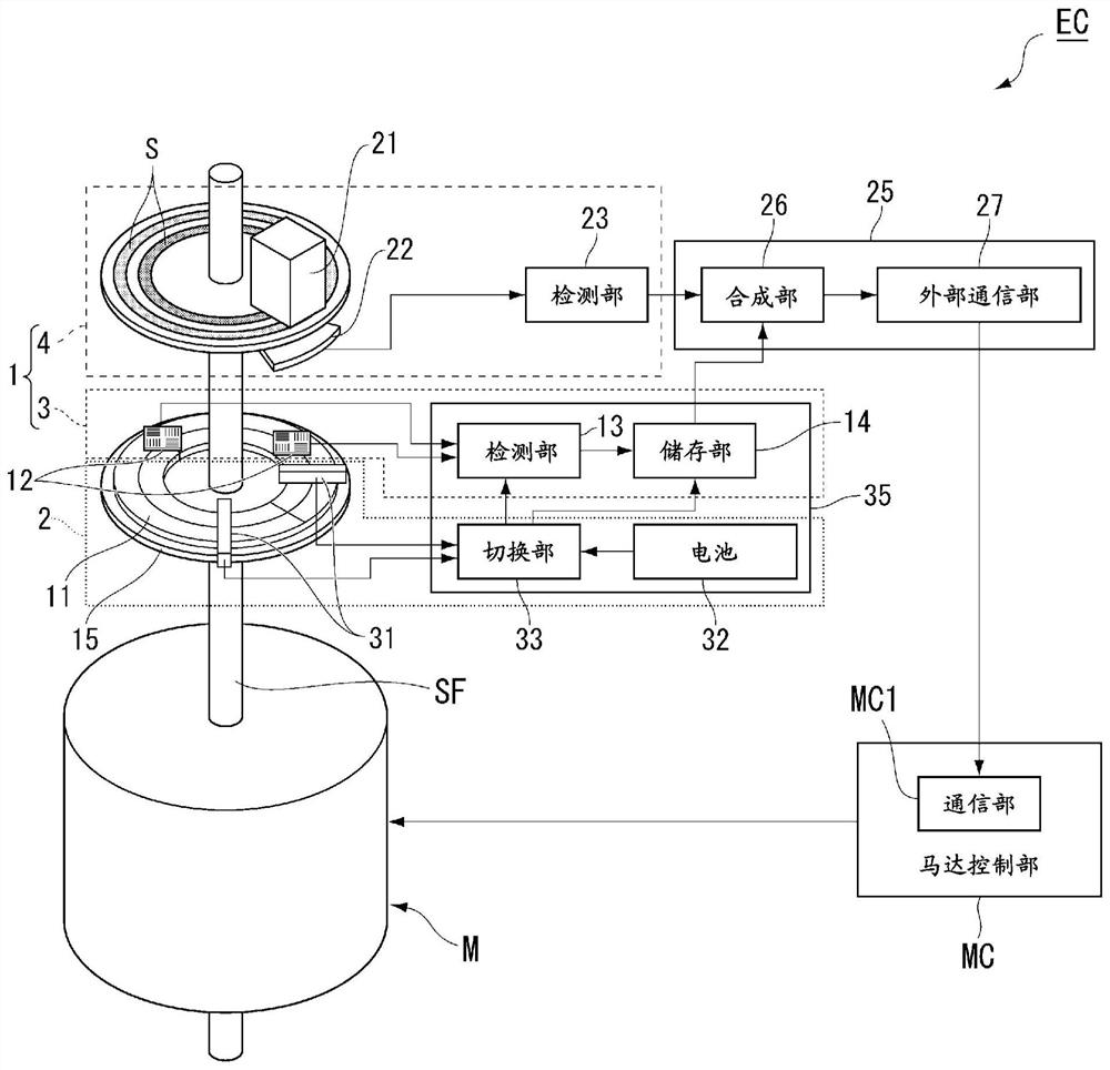
[0034] The first embodiment will be described. figure 1 It is a diagram showing the encoder device EC according to the present embodiment. This encoder device EC detects the rotational position information of the rotation shaft Sf (moving portion) of the motor M (powertrain). The rotating shaft SF is, for example, the rotating shaft (rotor) of the motor M, but may be a power transmitting portion having a transmission or the like and a rotating shaft (output shaft) of the motor M. The rotational position information detected by the encoder device EC is supplied to the motor control unit MC. The motor control unit MC controls the rotation of the motor M using the rotational position information supplied from the encoder device EC. The motor control unit MC controls the rotation of the rotating shaft Sf.
[0035] The encoder device EC includes a position detection system 1 and a power supply system 2. The position detection system 1 detects the rotational position information of the ...
no. 2 approach
[0088] The second embodiment will be described. In the present embodiment, the same configuration as the above-described embodiment is labeled, omitted or simplified. Figure 6 It is a diagram showing the encoder device EC according to the present embodiment. In the present embodiment, the battery 32 includes a primary battery 36 and a secondary battery 37. The motor control unit MC includes a power supply unit MC2, and the secondary battery 37 is charged by the electric power supplied from the power supply portion MC2. The power supply unit MC2, for example, a power supply to the drive of the drive of the rotary shaft Sf (moving portion), supplies power to the motor M. The secondary battery 37 may also be charged from the power supply unit MC2 to receive power from the power supply unit MC2 by the power supply unit MC2 to supply power to the motor M (for example, the main power source is turned on). Further, at least a portion of the electricity battery 37 is generated by the elec...
no. 3 approach
[0097] A third embodiment will be described. In the present embodiment, the same configuration as the above-described embodiment is labeled, omitted or simplified. Figure 8 It is a diagram showing the encoder device EC according to the present embodiment. The rotational position information of the multi-rotating information detecting unit 3 on the rotation axis Sf (moving portion) is magnetically detected in the first embodiment, and in the present embodiment, it is optically detected.
[0098] The multi-rotating information detecting unit 3 includes a dial disk S, a light-emitting element 21 (irradiation portion), and a light receiving sensor 22 (photodetector).
[0099] The scale disk S is bound to the rotating shaft Sf. The light-emitting element 21 is irradiated with the tick disk S. In a state where the supply element 21 is disconnected in a state where the power from the external power from the encoder device EC is disconnected, the light is irradiated using the power suppli...
PUM
 Abstract
Description
Claims
Application Information
 - R&D
- Intellectual Property
- Life Sciences
- Materials
- Tech Scout
- Unparalleled Data Quality
- Higher Quality Content
- 60% Fewer Hallucinations
Browse by: Latest US Patents, China's latest patents, Technical Efficacy Thesaurus, Application Domain, Technology Topic, Popular Technical Reports.
© 2025 PatSnap. All rights reserved.Legal|Privacy policy|Modern Slavery Act Transparency Statement|Sitemap|About US| Contact US: help@patsnap.com