Finished product rotating speed detection device and detection method for motor production

A speed detection and finished product technology, applied in measuring devices, linear/angular velocity measurement, velocity/acceleration/impact measurement, etc., can solve problems such as lack of design rationality, unfavorable efficient detection of motors, and high physical consumption of operators, etc., to achieve Reduce physical energy consumption, facilitate efficient detection operations, and facilitate the effect of operations

Inactive Publication Date: 2021-07-09
杨洋
View PDF0 Cites 2 Cited by
  • Summary
  • Abstract
  • Description
  • Claims
  • Application Information

AI Technical Summary

Problems solved by technology

[0006] The purpose of the present invention is to provide a finished product speed detection device for motor production, to solve the lack of rationality in the design of the fixing device for the motor to be detected proposed in the above background technology, the manual work of the operator is required in the process of clamping and fixing the motor, and the Operators consume a lot of physical energy, which is not conducive to the efficient detection of motors.

Method used


Image

  • Finished product rotating speed detection device and detection method for motor production
  • Finished product rotating speed detection device and detection method for motor production
  • Finished product rotating speed detection device and detection method for motor production

Examples


Embodiment 1

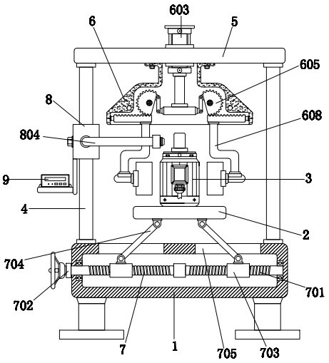
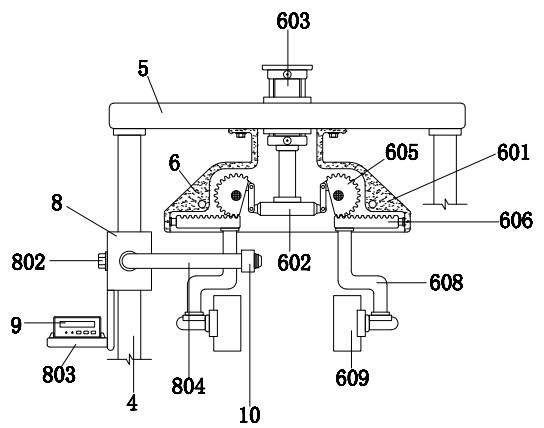
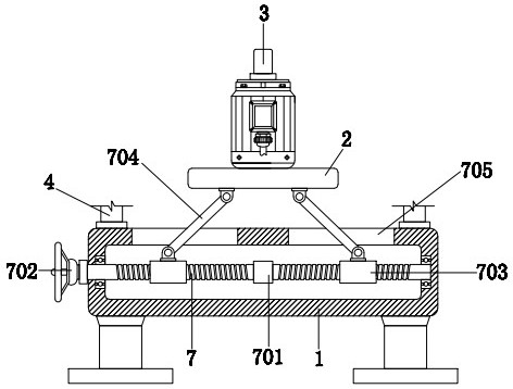
[0034] A finished product speed detection device for motor production, comprising a cavity plate 1, a supporting plate 2 is arranged above the upper surface of the cavity plate 1, a motor 3 is placed on the upper surface of the supporting plate 2, and the four corners of the upper surface of the cavity plate 1 are A column 4 is provided, the bottom of the column 4 is fixedly connected with the upper surface of the cavity plate 1, the top of the column 4 is provided with a top plate 5, the lower surface of the top plate 5 is fixedly connected with the top of the column 4, and a clip is provided below the top plate 5. Clamping mechanism 6, body 9 is provided on the left side of the outer wall of left column 4, and probe 10 is provided on the right side of body 9, and clamping mechanism 6 includes housing 601, horizontal strip plate 602, hydraulic cylinder 603, rotating rod 604, gear 605 , tooth bar 606, square bar 607, connecting rod 608, splint 609 and rubber ball 610, housing 6...

Embodiment 2

[0036] As an option, seefigure 1 with 3 , the finished product speed detection device for motor production, the carriage 2 is connected with the cavity plate 1 through the support mechanism 7, the support mechanism 7 includes a screw rod 701, a knob 702, a sleeve 703, an inclined rod 704 and a through groove 705, and the screw rod 701 Located inside the cavity plate 1, the screw rod 701 is rotationally connected with the cavity plate 1 through a ball bearing. The left end of the screw rod 701 is provided with a knob 702, and the knob 702 is fixedly connected with the contact surface of the screw rod 701. The screw rod 701 Sleeves 703 are sleeved on the left and right sides of the outer wall of the sleeve 703, the inner wall of the sleeve 703 is threadedly connected with the outer wall of the screw rod 701, and the top of the outer wall of the sleeve 703 is hinged with a slanting rod 704, and the slanting rod 704 runs through the housing 601 through the slot 705. , the outer wa...

Embodiment 3

[0039] As an option, see figure 1 , 2 And 5, the finished product speed detection device for motor production, the outer wall of the vertical rod 4 is provided with an adjustment mechanism 8, the two sides of the adjustment mechanism 8 are connected with the body 9 and the probe 10 respectively, the adjustment mechanism 8 includes a vertical tube 801, a bolt 802, The supporting plate 803 and the bent rod 804, the vertical tube 801 is sleeved on the outer wall of the left vertical bar 4, the inner wall of the vertical tube 801 is matched with the outer wall of the left vertical bar 4, and the left side of the outer wall of the vertical tube 801 is threaded with a bolt 802 , the bolt 802 penetrates a part of the vertical tube 801 and is tight against the outer wall of the left vertical rod 4, and the left side of the bottom end of the vertical tube 801 is fixedly connected with a supporting plate 803, and the upper surface of the supporting plate 803 is fixed to the lower surfac...


PUM


Abstract

A finished product rotating speed detection device for motor production disclosed by the present invention comprises a cavity plate, a supporting plate is arranged above the upper surface of the cavity plate, a motor is placed on the upper surface of the supporting plate, stand columns are arranged at four corners of the upper surface of the cavity plate, and the bottom ends of the stand columns are fixedly connected with the upper surface of the cavity plate. A top plate is arranged at the top ends of the stand columns. According to the finished product rotating speed detection device for motor production, through cooperation of a cavity plate, a supporting plate, a motor, a stand column, a top plate and a clamping mechanism, two tooth strips, a connecting rod and a clamping plate can move towards the inner side together, rubber balls on the inner side surface of the clamping plate can abut against the outer wall of the motor, and then clamping and fixing operation on the motor to be detected is completed; during the period, manual clamping operation of an operator is not needed, physical consumption of the operator is reduced, and efficient detection operation of the motor is facilitated.

Description

technical field [0001] The invention relates to the technical field of motor production and processing, in particular to a finished product speed detection device for motor production. Background technique [0002] An electric motor is a rotary electric machine that converts electrical energy into mechanical energy and mainly includes an electromagnet winding or distributed stator winding for generating a magnetic field and a rotating armature or rotor. Under the action of the rotating magnetic field of the stator winding, there is a current passing through the effective side of the stator winding and it is caused to rotate by the action of the magnetic field. After the motor is produced, it needs to carry out multi-process inspections before leaving the factory. Only after passing the test can it be allowed to leave the factory for sale. The speed detection of the finished motor is an important detection step, but there are still some disadvantages in the actual operation p...

Claims


Application Information

Patent Timeline
Patent Type & Authority Applications(China)
IPC IPC(8): G01P3/00G01P1/00
CPCG01P1/00G01P3/00
Inventor 杨洋
Owner 杨洋
Why Eureka
Try Eureka