
Laser receiving system and laser radar

A laser receiving and laser technology, used in radio wave measurement systems, instruments, etc., can solve the problems of limited reflected laser light and difficulty in increasing the ranging distance of optical phased array lidar, so as to improve the receiving efficiency and expand the receiving field of view. , the effect of expanding the receiving aperture

Pending Publication Date: 2021-07-09
SUTENG INNOVATION TECH CO LTD
View PDF8 Cites 0 Cited by
  • Summary
  • Abstract
  • Description
  • Claims
  • Application Information

AI Technical Summary

Problems solved by technology

[0004] However, during the research process, the inventors of the present application found that in the existing optical phased array laser radar, due to the very limited receiving aperture, the received reflected laser light is very limited, and the ranging distance of the optical phased array laser radar is very short. Difficult to increase

Method used


Image

  • Laser receiving system and laser radar
  • Laser receiving system and laser radar
  • Laser receiving system and laser radar

Examples


Embodiment Construction

[0031] Embodiments of the technical solutions of the present invention will be described in detail below in conjunction with the accompanying drawings. The following examples are only used to illustrate the technical solutions of the present invention more clearly, and therefore are only examples, rather than limiting the protection scope of the present invention.

[0032] It should be noted that, unless otherwise specified, the technical terms or scientific terms used in this application shall have the usual meanings understood by those skilled in the art to which the present invention belongs.

[0033] In the description of the present application, it should be understood that the terms "center", "longitudinal", "transverse", "length", "width", "thickness", "upper", "lower", "front", " Back", "Left", "Right", "Vertical", "Horizontal", "Top", "Bottom", "Inner", "Outer", "Clockwise", "Counterclockwise", "Axial", The orientation or positional relationship indicated by "radial"...


PUM


Abstract

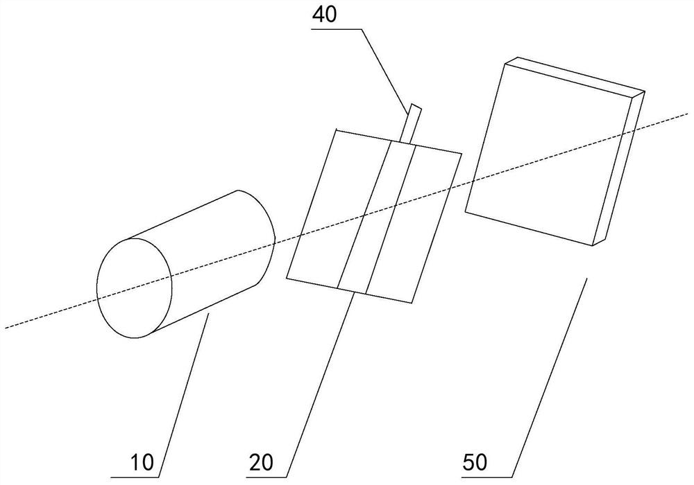
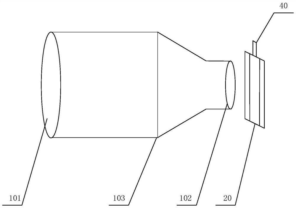
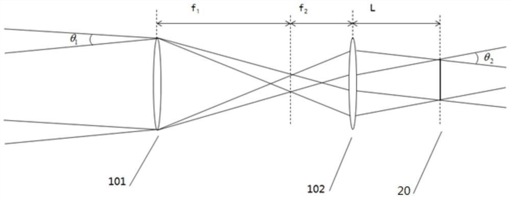
The embodiment of the invention relates to the technical field of laser radars, in particular to a laser receiving system and a laser radar. The laser receiving system comprises a receiving mirror group, a receiving antenna array, a light detector and a controller; the receiving mirror group is used for receiving the reflected laser and converging the reflected laser to the receiving antenna array; the receiving antenna array is used for receiving the converged reflected laser; the optical detector is used for receiving the reflected laser received by the receiving antenna array and converting the reflected laser into an electric signal; and the controller is used for processing the electric signal. Through the system, the laser radar receiving efficiency is improved.

Description

technical field [0001] Embodiments of the present invention relate to the technical field of laser radar, in particular to a laser receiving system and laser radar. Background technique [0002] Lidar is a radar system that emits laser beams to detect the position, speed and other characteristic quantities of objects. Its working principle is that the transmitting system first emits the outgoing laser for detection to the detection area, and then the receiving system receives the reflection from the objects in the detection area. The reflected laser is compared with the outgoing laser, and the relevant information of the object can be obtained after processing, such as distance, orientation, height, speed, attitude, and even shape and other parameters. [0003] Optical phased array (Optical Phase Array, OPA) lidar, as a kind of pure solid-state lidar, prepares optical waveguide channels and transmitting and receiving antenna arrays on silicon-based chips. The phase of the t...

Claims


Application Information

Patent Timeline
Patent Type & Authority Applications(China)
IPC IPC(8): G01S7/481
CPCG01S7/4816
Inventor 侯昌韬
Owner SUTENG INNOVATION TECH CO LTD
Learn More