Eureka AIR delivers breakthrough ideas for toughest innovation challenges, trusted by R&D personnel around the world.

Positioning measurement method and system for thin-wall rotary body machining automatic production line

An automatic production line and thin-walled rotary technology, which is applied in the direction of metal processing equipment, measuring/indicating equipment, metal processing machinery parts, etc., can solve the problem of low measurement accuracy, inability to use CNC system processing, and inability to realize circumferential rotation positioning measurement, etc. problem, to achieve the effect of automatic acquisition, measurement and adjustment of circumferential rotation

Active Publication Date: 2021-07-13
SHANGHAI SPACE PRECISION MACHINERY RES INST
View PDF10 Cites 0 Cited by
  • Summary
  • Abstract
  • Description
  • Claims
  • Application Information

AI Technical Summary

Problems solved by technology

The disadvantage is that the measurement data needs to be compiled by C++ language and then poured into UG for processing, which cannot be processed by the numerical control system, and the circumferential rotation positioning measurement cannot be realized
The disadvantage is that the environment has a great influence on the laser sensor, the measurement accuracy is lower than that of the contact on-machine measurement probe, and the circumferential rotation positioning measurement cannot be realized

Method used


Image

  • Positioning measurement method and system for thin-wall rotary body machining automatic production line
  • Positioning measurement method and system for thin-wall rotary body machining automatic production line
  • Positioning measurement method and system for thin-wall rotary body machining automatic production line

Examples


Embodiment Construction

[0086] The present invention will be described in detail below in conjunction with specific embodiments. The following examples will help those skilled in the art to further understand the present invention, but do not limit the present invention in any form. It should be noted that those skilled in the art can make several changes and improvements without departing from the concept of the present invention. These all belong to the protection scope of the present invention.

[0087] The embodiment of the present invention provides a positioning measurement method for the automatic production line of thin-walled rotary machining, such as figure 1 As shown, first measure the points on the section of the rotating body and calculate the coordinates, including:

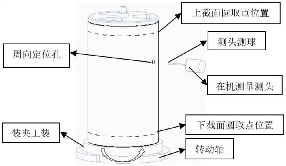
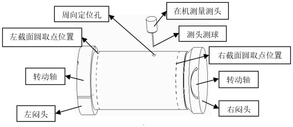
[0088] Such as figure 2 and image 3 As shown, in the process of vertical positioning measurement, the cylindrical rotating body includes the position of the upper cross-section circle and the lower cross-section circ...


PUM


Abstract

The invention provides a positioning measurement method and system for a thin-wall rotary body machining automatic production line, and relates to the technical field of numerical control machine tool on-machine measurement. The method comprises the following steps of S1, measuring points on the section of a rotary body, and calculating coordinates; S2, according to the coordinates of the points on the section of the rotary body, calculating the rotary body axis clamping inclination and the section circle clamping eccentricity; S3, using a numerical control system macro program for judging whether the rotary body axis clamping inclination and the section circle clamping eccentricity meet the tolerance requirement or not; and S4, adjusting the circumferential rotation angle through rotary body circumferential rotation measurement, macroprogram calculation and angle feedback compensation in sequence. According to the positioning measurement method and system, the diameter and the circle center value of the section circle can be obtained through multi-point measurement, the circumferential rotation angle is obtained through measurement and calculation of the outer wall circumferential positioning hole and feedback adjustment is carried out, the deviation between the actual circle center and the theoretical axis of the rotary body is obtained through measurement of the circle center of the section circle of the rotary body, and qualification judgment can be carried out on the on-machine measurement result through the macro program.

Description

technical field [0001] The invention relates to the technical field of on-machine measurement of numerical control machine tools, in particular to a positioning measurement method and system for an automatic production line of machining of thin-walled rotary bodies. In particular, it involves the measurement of cylindrical section, the clamping tilt and eccentricity measurement of the axis of the rotary body, the measurement calculation and feedback adjustment of the circumferential rotation, and the macro program calculation and judgment of the measurement results. Background technique [0002] In order to ensure the automatic production of the production line, it is necessary to measure the positioning of the rotating body before processing, and judge whether the clamping is qualified. In the past, when measuring the rotating body installed on the turntable, the coordinates of the center of the circle could not be obtained through multi-point measurement, there was no meas...

Claims


Application Information

Patent Timeline
Patent Type & Authority Applications(China)
IPC IPC(8): B23Q17/00
CPCB23Q17/003
Inventor 金路成群林李建华曹忠穆英娟孔志学张永升任培强姜恒
Owner SHANGHAI SPACE PRECISION MACHINERY RES INST
Why Eureka
Eureka Blog
Learn More