Machining equipment for injection mold casting

A technology for processing equipment and injection molds, applied in the direction of coating, etc., can solve the problems of rough surface of castings, etc., and achieve the effects of high specific strength/specific stiffness, high connection strength, and good thermal conductivity.

Inactive Publication Date: 2021-07-13
广州盈在科技有限公司
View PDF0 Cites 2 Cited by
  • Summary
  • Abstract
  • Description
  • Claims
  • Application Information

AI Technical Summary

Problems solved by technology

[0002] Casting mold means that in order to obtain the structural shape of the part, other easy-to-form materials are used to make the structural shape of the part in advance, and then the mold is placed in the sand mold, so a cavity with the same structural size as the part is formed in the sand mold. Then pour a fluid liquid into the cavity. After the liquid cools and solidifies, it can form a part with exactly the same shape and structure as the mold. Casting molds are an important part of the casting process. However, in actual operation, castings often appear After the casting is completed, the surface of the casting is rough and not smooth. A large part of this problem is due to the reaction between the casting and the cavity of the injection mold, which makes the surface of the injection mold bond part of the casting.

Method used


Image

  • Machining equipment for injection mold casting
  • Machining equipment for injection mold casting

Examples


Embodiment 1

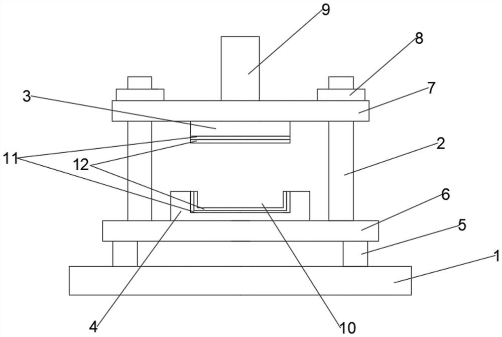
[0032] A processing equipment for injection mold casting, comprising a fixed base plate 1, a guide column 2, an upper mold 3 and a lower mold 4, the upper surface of the fixed base plate 1 is fixedly provided with several fixed columns 5, and the upper end of the fixed column 5 is provided with a support plate 6; the upper end of the guide column 2 is provided with a connecting plate 7 parallel to the support plate 6, the guide column 2 passes through the connecting plate 7 and the connecting plate 7 is fixed on the upper end of the guiding column 2 by fastening bolts 8; the upper end of the connecting plate 7 A hydraulic rod 9 is provided at the center of the side, and an upper mold 3 is provided at the center of the lower side of the connecting plate 7. The hydraulic rod 9 passes through the connecting plate 7 and is fixedly connected with the upper mold 3. The lower position of the upper mold 3 is correspondingly provided with The lower mold 4, the lower mold 4 is fixedly ar...

Embodiment 2

[0049] A processing equipment for injection mold casting, comprising a fixed base plate 1, a guide column 2, an upper mold 3 and a lower mold 4, the upper surface of the fixed base plate 1 is fixedly provided with several fixed columns 5, and the upper end of the fixed column 5 is provided with a support plate 6; the upper end of the guide column 2 is provided with a connecting plate 7 parallel to the support plate 6, the guide column 2 passes through the connecting plate 7 and the connecting plate 7 is fixed on the upper end of the guiding column 2 by fastening bolts 8; the upper end of the connecting plate 7 A hydraulic rod 9 is provided at the center of the side, and an upper mold 3 is provided at the center of the lower side of the connecting plate 7. The hydraulic rod 9 passes through the connecting plate 7 and is fixedly connected with the upper mold 3. The lower position of the upper mold 3 is correspondingly provided with The lower mold 4, the lower mold 4 is fixedly ar...

Embodiment 3

[0066] A processing equipment for injection mold casting, comprising a fixed base plate 1, a guide column 2, an upper mold 3 and a lower mold 4, the upper surface of the fixed base plate 1 is fixedly provided with several fixed columns 5, and the upper end of the fixed column 5 is provided with a support plate 6; the upper end of the guide column 2 is provided with a connecting plate 7 parallel to the support plate 6, the guide column 2 passes through the connecting plate 7 and the connecting plate 7 is fixed on the upper end of the guiding column 2 by fastening bolts 8; the upper end of the connecting plate 7 A hydraulic rod 9 is provided at the center of the side, and an upper mold 3 is provided at the center of the lower side of the connecting plate 7. The hydraulic rod 9 passes through the connecting plate 7 and is fixedly connected with the upper mold 3. The lower position of the upper mold 3 is correspondingly provided with The lower mold 4, the lower mold 4 is fixedly ar...


PUM

PropertyMeasurementUnit
thermal conductivityaaaaaaaaaa

Abstract

The invention relates to machining equipment for injection mold casting. The equipment comprises a fixed bottom plate, guide columns, an upper mold and a lower mold, a plurality of fixed columns are fixedly arranged on the upper surface of the fixed bottom plate, and a supporting plate is arranged at the upper ends of the fixed columns; the lower mold is correspondingly arranged below the upper mold, the lower mold is fixedly arranged above the supporting plate, and a cavity of a concave structure is formed in the upper surface of the lower mold; and the lower surface of the upper mold and the surface of the cavity are each provided with an easy-to-demold layer, and each easy-to-demold layer comprises a reinforcing layer and an anti-adhesion layer which are sequentially arranged from inside to outside. According to the machining equipment for injection mold casting, the machining equipment for injection mold casting is arranged to be of an integrated structure of the fixed bottom plate, the guide columns, the upper mold and the lower mold, the fixed bottom plate and the guide columns play a supporting and fixing role, so that normal operation of the upper mold and the lower mold is guaranteed, the overall structure is firmer through the connection relation of the guide columns, the supporting plate and a connecting plate, the connecting strength is high, and collapse and falling are not prone to occurring in the using process.

Description

technical field [0001] The invention relates to the field of casting mold processing equipment, in particular to a processing equipment for injection mold casting. Background technique [0002] Casting mold means that in order to obtain the structural shape of the part, other easy-to-form materials are used to make the structural shape of the part in advance, and then the mold is placed in the sand mold, so a cavity with the same structural size as the part is formed in the sand mold. Then pour a fluid liquid into the cavity. After the liquid cools and solidifies, it can form a part with exactly the same shape and structure as the mold. Casting molds are an important part of the casting process. However, in actual operation, castings often appear After the casting is completed, the surface of the casting is rough and not smooth. A large part of the reason for this problem is that the casting reacts with the cavity of the injection mold, so that part of the casting is bonded ...

Claims


Application Information

Patent Timeline
Patent Type & Authority Applications(China)
IPC IPC(8): B29C33/56B29C33/30B29C45/26
CPCB29C33/30B29C33/56B29C45/26B29C45/2606
Inventor 魏思宝
Owner 广州盈在科技有限公司
Why Eureka
Try Eureka