

Mounting component for driving motor of electric automobile
A technology for driving motors and installing components, applied in vehicle components, electric power units, power units, etc., can solve problems such as tilting and inconvenient assembly, and achieve the effect of increasing the calibration range and facilitating assembly.
- Summary
- Abstract
- Description
- Claims
- Application Information
AI Technical Summary
Problems solved by technology
Method used
Image

Examples
Embodiment 1
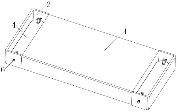
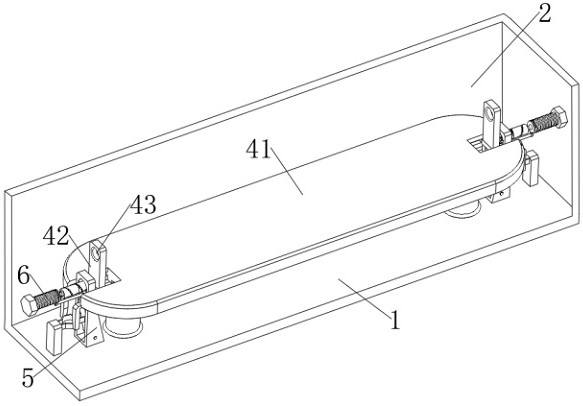
[0028] see Figure 1-Figure 4 , an electric vehicle drive motor installation component, including a connection plate 1 and a placement groove 2 opened on the connection plate 1, a support device 4 for supporting the drive motor is slidably connected in the placement groove 2, and the support device 4 includes a support plate 41, The support plate 41 is slidably connected in the placement groove 2, the support plate 41 is provided with a square groove 77, and in the square groove 77 is connected with the turning plate 42 through the rotation of the second rotating shaft 44, and the turning plate 42 is provided with the first through hole 43;
[0029] An extrusion device 5 for limiting the support device 4 is also fixedly installed in the placement groove 2, the extrusion device 5 is located below the support device 4, and a fixing device 6 is screwed on the connecting plate 1, and the fixing device 6 can penetrate through the extrusion The device 5 cooperates with the first thr...
Embodiment 2
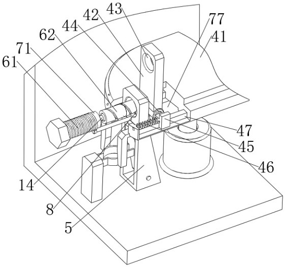
[0034] This embodiment is an improvement made on the basis of Embodiment 1. A T-shaped chute 47 is also provided on the support plate 41. The T-shaped chute 47 is located on one side of the square groove 77, and the T-shaped chute 47 is slidingly connected. There is a T-shaped slider 45 , which is connected to the support plate 41 through a spring 46 , and the T-shaped slider 45 is also connected to the second rotating shaft 44 .
[0035]In this example:
[0036] Primary clamping: According to image 3 As shown, a T-shaped chute 47 is also provided on the support plate 41, and the T-shaped chute 47 is connected with the second rotating shaft 44. When the pressing device 5 lifts the turning plate 42 and rotates it, the support plate 41 will always drop. Since the width of the extruding device 5 gradually increases from the support plate 41 to the bottom of the placement groove 2, the extruding device 5 will gradually extrude the turning plate 42 to slide from the fixing device...
Embodiment 3
[0038] This embodiment is an improvement made on the basis of Embodiment 1. The extruding device 5 includes a trapezoidal platform 51, which is fixedly connected in the connection plate 1, and the trapezoidal platform 51 is rotatably connected with an extruding plate 52.
[0039] In this example:
[0040] Secondary clamping: According to image 3 with Figure 4 As shown, the trapezoidal platform 51 is used to squeeze the turnover plate 42. At this time, the turnover panel 42 slides and clamps the motor connection seat 15, but there is only one stress point between the turnover panel 42 and the trapezoidal platform 51, which will cause the turnover panel to 42 is also a point of force when clamping the motor connection seat 15. When the motor connection seat 15 is subjected to an external force, it will be offset, resulting in the failure of the rotation calibration of the turnover plate 42 in the above steps. Therefore, there is a Extrusion plate 52, by rotating extrusion p...
PUM
 Abstract
Description
Claims
Application Information