A special self-locking spreader for steel structure

A steel structure and spreader technology, applied in the direction of load hanging components, transportation and packaging, etc., can solve the problems of reducing risks, achieve the effects of reducing risks, simple operation, and ensuring stability

Active Publication Date: 2022-07-26
XINJIANG SUZHONG CONSTR ENG
View PDF4 Cites 0 Cited by
  • Summary
  • Abstract
  • Description
  • Claims
  • Application Information

AI Technical Summary

Problems solved by technology

[0004] In order to overcome the deficiency in the prior art that steel components need to be manually released from the steel wire rope bound between the lifting point of the component and the hook of the tower crane after the steel component is hoisted in place, the present invention provides a special self-locking hoist for steel structures. The binding connection and unbinding process between the hooks of the lifting equipment are all completed by the staff on the ground, which avoids the risk of construction workers climbing up and down. At the same time, the hanging lock mechanism has a locking effect on the fixed bolt, forming an insurance effect. Reduces the risk that the first tie rod will not be unhooked due to human mishandling of the pull cord

Method used


Image

  • A special self-locking spreader for steel structure
  • A special self-locking spreader for steel structure
  • A special self-locking spreader for steel structure

Examples


Embodiment 1

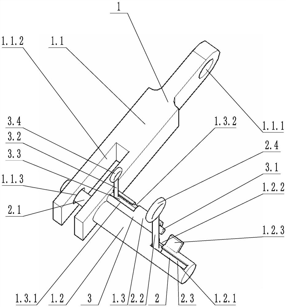
[0031] like image 3 As shown, a special self-locking spreader for steel structures includes a spreader body 1, a fixing structure 2, a locking structure 3 and a pull rope 4. The spreader body 1 includes a connecting block 1.1, a first sleeve 1.2 and a second set of Pipe 1.3, the axis of the first sleeve 1.2 is perpendicular to the axis of the second sleeve 1.3, the connecting block 1.1 is provided with a jack 1.1.3, the jack 1.1.3 transversely passes through the connecting groove 1.1.2, the first sleeve 1.2 The side wall is provided with a first sliding groove 1.2.1 and a first locking groove 1.2.2 that communicate with each other.

[0032] The fixed structure 2 includes a fixed pin 2.1, a first pull rod 2.2 and a first telescopic spring 2.3. The fixed pin 2.1 is arranged in the first sleeve 1.2 and is slidably connected with the first sleeve 1.2. The fixed pin 2.1 can be along the first sleeve 1.2. The axis rotates, one end of the fixed pin 2.1 passes through the jack 1.1.3...

Embodiment 2

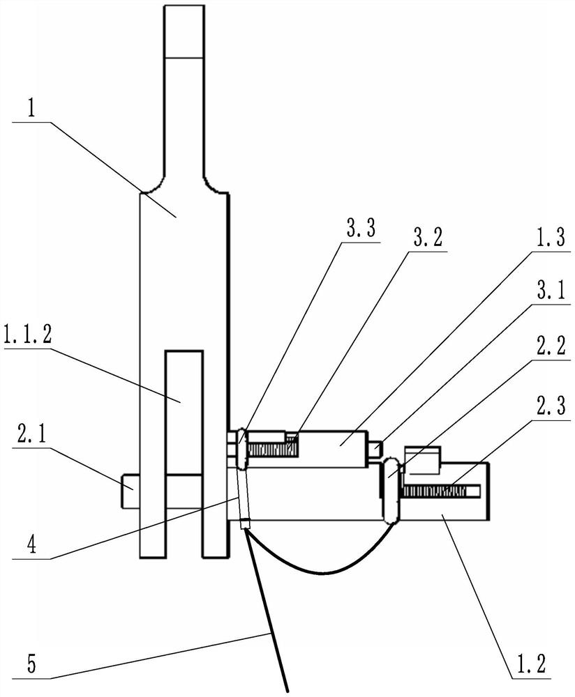
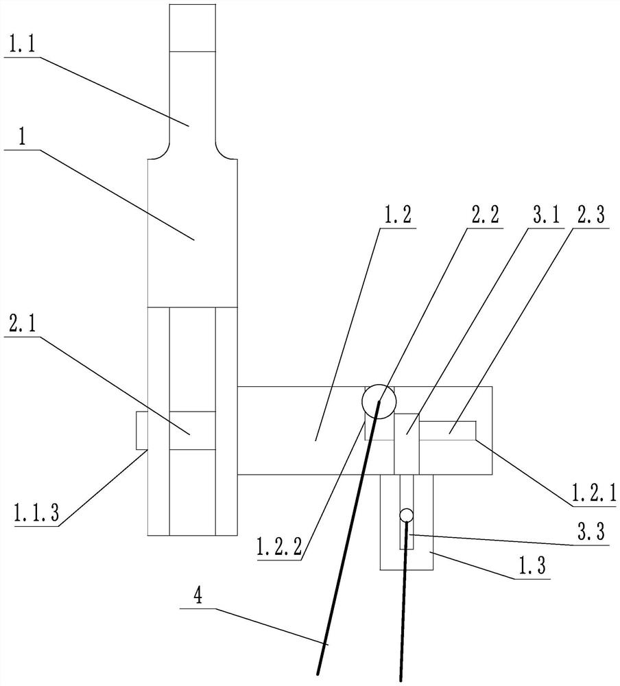
[0036] like figure 1 As shown, a special self-locking spreader for steel structures includes a spreader body 1, a fixing structure 2, a locking structure 3 and a pull rope 4. The spreader body 1 includes a connecting block 1.1, a first sleeve 1.2 and a second set of Pipe 1.3, the connecting block 1.1 is provided with a jack 1.1.3, a connecting hole 1.1.1 and a connecting groove 1.1.2, the jack 1.1.3 transversely passes through the connecting groove 1.1.2, on the side wall of the first sleeve 1.2 A first chute 1.2.1 and a first lock slot 1.2.2 communicated with each other are provided; the side wall of the second sleeve 1.3 is provided with a second chute 1.3.1 and a second lock slot 1.3.2 communicated with each other .

[0037] The fixed structure 2 includes a fixed pin 2.1, a first pull rod 2.2 and a first telescopic spring 2.3. The fixed pin 2.1 is arranged in the first sleeve 1.2 and is slidably connected with the first sleeve 1.2. The fixed pin 2.1 can be along the first ...

Embodiment 3

[0041] like figure 1 and figure 2 As shown, on the basis of Embodiment 2, the first pull rod 2.2 and the second pull rod 3.2 are connected to the same pull rope 4; the second pull rod 3.2 is provided with an elastic elastic member 5, one end of the elastic elastic member 5 is connected to the second pull rod 5. The pull rod 3.2 is connected, and one end of the pull rope 4 is fixed with the elastic telescopic element 5 and then passes through the elastic telescopic element 5 and is connected to the first pull rod 2.2.

[0042] In the above technical solution, the elastic elastic member 5 may be a retractable spring or an elastic elastic cord or other elastic member. One end of the pull rope 4 is bound to the first pull rod 2.2, and after leaving an appropriate margin, it is knotted and then tied to the elastic telescopic element 5 on the second pull rod 3.2. The function of the elastic telescopic element 5 is to adjust the length of the rope between the two pull rods, and to...


PUM


Abstract

The invention discloses a special self-locking spreader for steel structures, comprising: a spreader body, a fixing structure, a lifting lock mechanism and a pull rope. The spreader body includes a connecting block and a first sleeve, and the connecting block is provided with a jack and a connecting hole, the side wall of the first sleeve is provided with a first sliding groove and a first locking groove that communicate with each other; the fixing structure includes a fixed latch, a first pull rod and a first telescopic spring, and the fixed latch is arranged in the first sleeve and It is slidably connected with the first sleeve; the locking mechanism includes a sliding block, a third telescopic spring and an extension block, the sliding block is slidably connected with the connecting block, one end of the extension block is fixed with the sliding block, and the other end of the extension block is provided with a first locking The first locking block is in contact with the first pull rod; the first pull rod is connected with the pull rope. The invention provides a special self-locking hanger for steel structure, which avoids the risk of construction personnel climbing up and down, and the hanging lock mechanism has a locking effect on the fixed bolt, so that the first pull rod will not be unhooked due to human misoperation of the pull rope .

Description

technical field [0001] The invention relates to the technical field of engineering construction, in particular to a special self-locking hanger for steel structures. Background technique [0002] In the construction of traditional steel structure house construction, steel columns and steel plate walls are generally installed once every three floors. The height of a single steel member is high, and the cross-section is mostly elongated; when the steel member is hoisted in place, it needs to be manually lifted. The wire rope tied between the point and the tower crane hook. Since there is no safety ladder for the construction personnel to go up and down vertically in this process, the construction personnel mostly use the original climbing method. Column, since the height of individual components is more than 9 meters, there is a risk of falling from a high place due to fatigue or mishandling during the climbing process, and the tools used in the process of untying the wire ro...

Claims


Application Information

Patent Timeline
Patent Type & Authority Patents(China)
IPC IPC(8): B66C1/10
CPCB66C1/10
Inventor 顾李平曹国军白小松
Owner XINJIANG SUZHONG CONSTR ENG
Why Eureka
Try Eureka