Programmable stepped electronic equipment heat dissipation temperature control film

An electronic device, a stepped technology, applied in the field of temperature control films, can solve the problems of material leakage, fast heat conduction, and high heat source temperature, and achieve the effects of ensuring safe use temperature, reducing heat source temperature, and simple overall structure.

Pending Publication Date: 2021-07-13
SUZHOU ENBRIGHTECH
View PDF0 Cites 2 Cited by
  • Summary
  • Abstract
  • Description
  • Claims
  • Application Information

AI Technical Summary

Problems solved by technology

[0004] 1. If the temperature of the heat source is too high, the heat conduction speed is too fast, and the efficiency is too high, there will be problems with the shell temperature being too high, which cannot meet the safety requirements;
[0005] 2. The temperature of the heat source is too high and the heat dissipation effect is not good. Although it will not cause the temperature of the shell to be too high, the temperature of the heat source cannot be effectively diffused, which seriously affects the service life of the equipment
[0006] The current heat conduction + single-layer heat storage temperature control will have the following problems: the temperature of the heat source is generally 90-100°C or even higher, and the temperature of the heat conduction layer may reach 80-90°C, so the heat storage at a high temperature point (about 80°C) is used alone The temperature control layer will not be able to meet the temperature requirements of the shell, and if the heat storage temperature control layer at a low temperature point (about 40°C) is used alone, material leakage will easily occur when the material is exposed to high temperature for a long time, and the safety factor will be reduced

Method used


Image

  • Programmable stepped electronic equipment heat dissipation temperature control film

Examples


Embodiment Construction

[0022] The embodiments of the present invention are described in detail below, so that the advantages and features of the present invention can be more easily understood by those skilled in the art, so as to define the protection scope of the present invention more clearly.

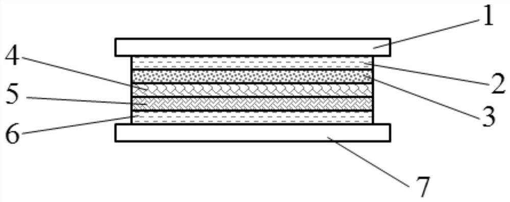
[0023] Such as figure 1 As shown, a programmable stepped heat dissipation and temperature control film for electronic equipment, including an upper release film layer 1, an upper acrylic adhesive layer 2, an elastomer heat-conducting layer 3, and a high phase change The point temperature control layer 4, the low phase transition point temperature control layer 5, the lower acrylic adhesive layer 6 and the lower release film layer 7, the size of the upper release film layer 1 and the lower release film layer 7 are not smaller than the upper acrylic Adhesive layer 2, elastomer heat conduction layer 3, high phase transition point temperature control layer 4, low phase transition point temperature control lay...


PUM

PropertyMeasurementUnit
thicknessaaaaaaaaaa
thicknessaaaaaaaaaa
thicknessaaaaaaaaaa

Abstract

The invention discloses a programmable stepped electronic equipment heat dissipation temperature control film which comprises an upper release film layer, an upper acrylic acid adhesive layer, an elastomer heat conduction layer, a high-phase-change-point temperature control layer, a low-phase-change-point temperature control layer, a lower acrylic acid adhesive layer and a lower release film layer which are sequentially attached from top to bottom. The size of the upper release film layer and the size of the lower release film layer are not smaller than the size of the upper acrylic acid adhesive layer, the size of the elastomer heat conduction layer, the size of the high-phase-change-point temperature control layer, the size of the low-phase-change-point temperature control layer and the size of the lower acrylic acid adhesive layer. The high-phase-change-point temperature control layer and the low-phase-change-point temperature control layer are arranged, the stepped heat conduction-temperature control-temperature control process is completed, the heat dissipation requirement and the safety regulation condition of the shell can be met, the temperature of a heat source can be effectively reduced, what is guaranteed is that the shell temperature meets the basic human body contact safety regulation requirement, and the safe use temperature of materials is guaranteed; the stability of the material is guaranteed, the service life of the material is prolonged, and the whole structure is simple and suitable for industrial popularization and application.

Description

technical field [0001] The invention belongs to the technical field of temperature control films, and in particular relates to a programmable stepped heat dissipation temperature control film for electronic equipment. Background technique [0002] Human-contact electronic equipment generates a lot of heat during operation. In order to prolong the service life of components in electronic equipment, heat conduction materials are generally used between components and radiators to conduct heat to electronic equipment. external. [0003] However, the traditional heat dissipation method has the following problems: [0004] 1. The temperature of the heat source is too high, the heat conduction speed is too fast, and the efficiency is too high, which will cause the problem of high shell temperature, which cannot meet the safety requirements; [0005] 2. The temperature of the heat source is too high and the heat dissipation effect is not good. Although the temperature of the shell...

Claims


Application Information

Patent Timeline
Patent Type & Authority Applications(China)
IPC IPC(8): C09J7/29H05K7/20
CPCC08K5/05C08K7/28C08K2003/2227C08K2201/011C09J2203/326C09J2425/006C09J2433/00C09J7/29H05K7/20
Inventor 谷旭夏红桃
Owner SUZHOU ENBRIGHTECH
Why Eureka
Try Eureka