Heat affected zone control device for high-frequency tempering equipment

A heat-affected zone and control device technology, applied in the mechanical field, can solve problems such as unstable control of the heat-affected zone, achieve balanced cooling effects, achieve stable control, and improve mechanical properties

Active Publication Date: 2021-07-13
YUHUAN BAOJIE MASCH CO LTD
View PDF2 Cites 0 Cited by
  • Summary
  • Abstract
  • Description
  • Claims
  • Application Information

AI Technical Summary

Problems solved by technology

[0005] The purpose of the present invention is to address the above-mentioned problems in the prior art, and propose a heat-affected zone control device for high-frequency tempering equipment, which solves the problem of unstable control of the heat-affected zone

Method used


Image

  • Heat affected zone control device for high-frequency tempering equipment
  • Heat affected zone control device for high-frequency tempering equipment
  • Heat affected zone control device for high-frequency tempering equipment

Examples


Embodiment 1

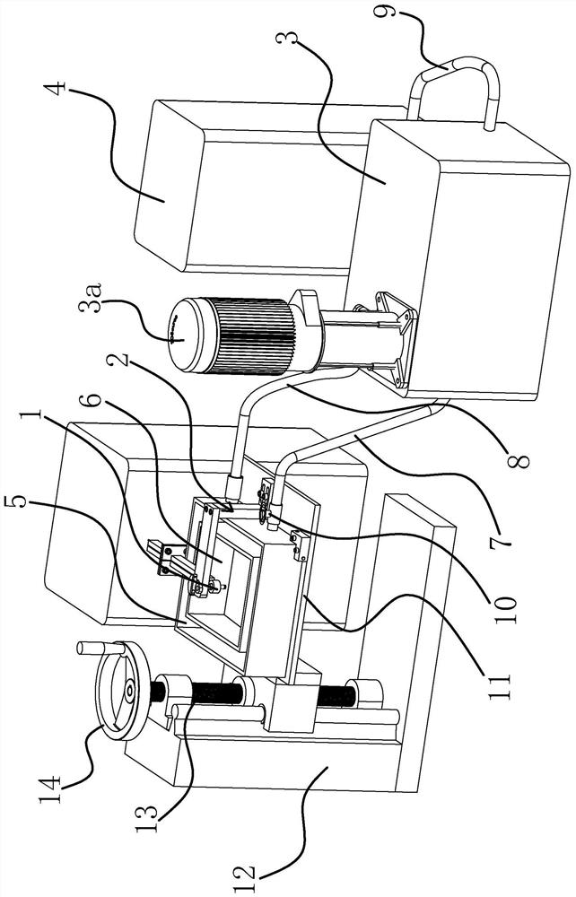
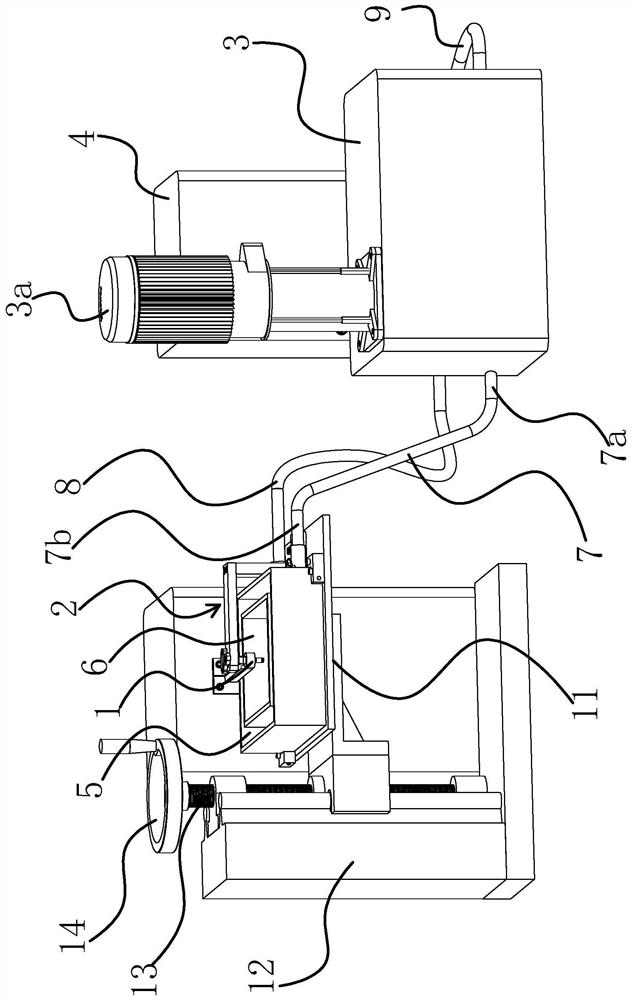
[0034] like figure 1 and figure 2As described above, the heat-affected zone control device used for high-frequency tempering equipment, the high-frequency tempering equipment includes a high-frequency induction coil 1 and a fixture 2, and the heat-affected zone control device includes a cooling liquid supply box 3, a liquid cooler 4, The overflow tank body 5 and the cooling tank body 6 located inside the overflow tank body 5, the cooling tank body 6 is located below the high-frequency induction coil 1, the clamp 2 is located above the high-frequency induction coil 1, the cooling liquid supply tank 3 and the cooling tank body 6 is connected with a medium inlet pipe 7, a return pipe 8 is connected between the liquid cooler 4 and the overflow tank body 5, and a medium pipe 9 is connected between the cooling liquid supply tank 3 and the liquid cooler 4. Specifically, the liquid cooler 4 adopts a water chiller model RHP-AD, and a water pump 3a is also arranged in the cooling liqu...

Embodiment 2

[0043] The structure and principle of this embodiment are basically the same as that of Embodiment 1, the difference is that in this embodiment, the clamp 2 is located in the cooling tank 6, specifically, the clamp 2 is a three-piece set in the cooling tank 6 Jaw Chuck. Usually, the heat-affected part on the part is divided into two ends. When controlling the accuracy of the heat-affected zone at the upward end of the part, the upward end of the part is clamped by the three-jaw chuck, and the end is immersed in the cooling liquid, so as to complete the heat-affected part on the upward end. The precision control of the heat-affected zone realizes the function that the device can control the precision of the heat-affected zone at both ends of the part.


PUM


Abstract

The invention provides a heat affected zone control device for high-frequency tempering equipment, and belongs to the technical field of machinery. The problem that control over a heat affected zone is unstable is solved. The heat affected zone control device for the high-frequency tempering equipment comprises a high-frequency induction coil and a fixture, and further comprises a cooling liquid supply box, a liquid cooler, an overflow tank body and a cooling tank body positioned on the inner side of the overflow tank body, wherein the cooling tank body is positioned below the high-frequency induction coil, the fixture is located above the high-frequency induction coil or located in the cooling tank body, a medium inlet pipe is connected between the cooling liquid supply box and the cooling tank body, a backflow pipe is connected between the liquid cooler and the overflow tank body, and a medium passing pipe is connected between the cooling liquid supply box and the liquid cooler. The heat affected zone control device for the high-frequency tempering equipment has the advantages that the cooling effect is balanced and uniform, and the heat affected zone can be stably controlled.

Description

technical field [0001] The invention belongs to the technical field of machinery, and relates to a heat-affected zone control device for high-frequency tempering equipment. Background technique [0002] With the continuous development of my country's automobile manufacturing industry, the manufacturing process requirements of some shaft parts that affect the performance of the whole machine are getting higher and higher, especially for some precision shaft parts that require high wear resistance. The mechanical properties and service life of the parts have a very important impact, and the current high-frequency tempering machine tools are mostly cooled by natural cooling after high-frequency tempering. This type of machine tool not only has the problem of long cooling time, Moreover, the length of the heat-affected zone cannot be controlled during high-frequency tempering. [0003] With the advancement of social science and technology, someone has invented a high-frequency te...

Claims


Application Information

Patent Timeline
Patent Type & Authority Applications(China)
IPC IPC(8): C21D11/00C21D1/10C21D1/18C21D9/30
CPCC21D11/005C21D1/10C21D1/18C21D9/0062C21D9/30Y02P10/25
Inventor 徐欣林志斌
Owner YUHUAN BAOJIE MASCH CO LTD
Why Eureka
Try Eureka