An anti-collision bar device for a license plate recognition barrier gate integrated machine

A license plate recognition and all-in-one technology, which is applied to the traffic control system of road vehicles, roads, roads, etc., can solve the problems of lack of support and protection structure, lack of substantial damage prevention function, and tilting of the pole body

Active Publication Date: 2022-04-12
深圳市强华威智能科技有限公司
View PDF6 Cites 0 Cited by
  • Summary
  • Abstract
  • Description
  • Claims
  • Application Information

AI Technical Summary

Problems solved by technology

[0005] The invention provides an anti-collision bar device for a license plate recognition barrier gate integrated machine, which aims to solve the problem that the existing anti-collision bar only has a warning record function for vehicles that forcibly pass through the barrier and lacks a substantial function of preventing damage. Secondly, the existing anti-collision bar Lack of support and protection structure, long-term relying on the quantitative thread control of the private server motor is prone to the problem of the rod body tilting and crooked

Method used


Image

  • An anti-collision bar device for a license plate recognition barrier gate integrated machine
  • An anti-collision bar device for a license plate recognition barrier gate integrated machine
  • An anti-collision bar device for a license plate recognition barrier gate integrated machine

Examples


Embodiment 1

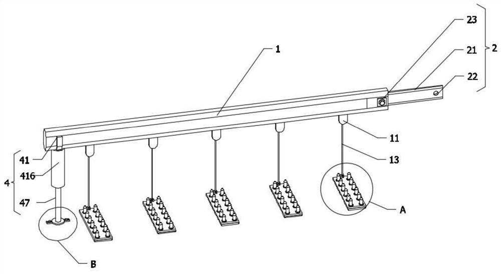
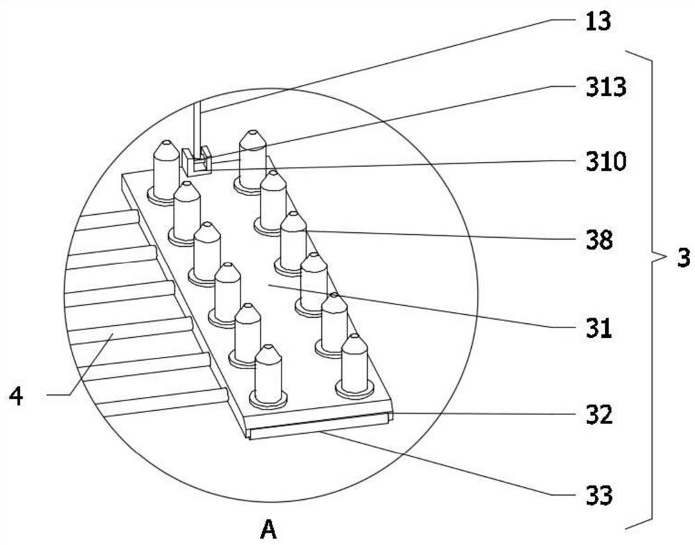
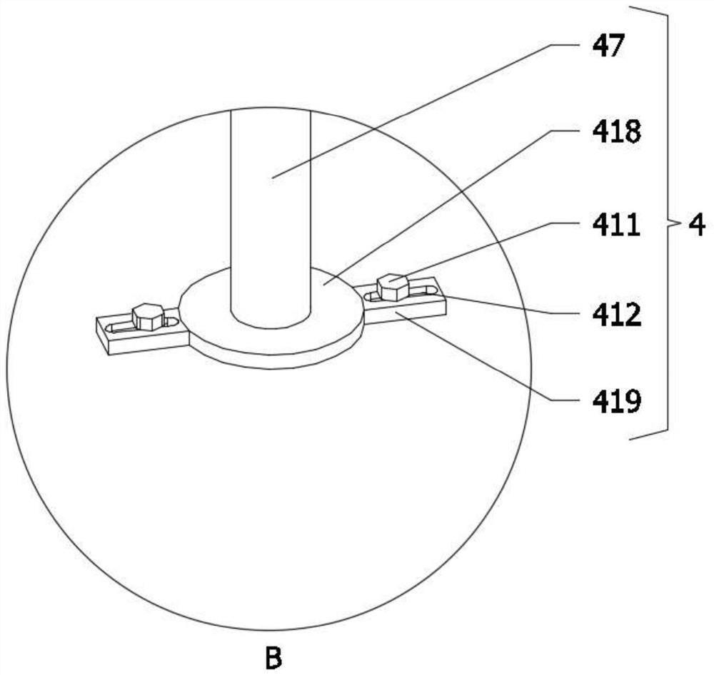
[0047] An anti-collision bar device for a license plate recognition barrier gate integrated machine, comprising a main body anti-collision bar 1 and a connecting mechanism 2, one end of the main body anti-collision bar 1 is provided with an insertion cavity, and the connection mechanism 2 is slidingly inserted into the insertion cavity , the lower part of the main body anti-collision cross bar 1 is provided with several limit mechanisms 3, and some limit mechanisms 3 all include a limit base plate 31, and several limit base plates 31 are provided with Install notch 32, all be provided with rotating roller 33 in some installing notches 32, the center positions of two ends of some rotating rollers 33 are all vertically fixedly connected with the first rotating shaft 34, and some first rotating shafts 34 are away from corresponding rotating roller One end of shaft 33 is all rotatably equipped with bearing 35, and the tops of some bearings 35 are all vertically fixedly installed wi...

Embodiment 2

[0057] as attached Figure 13 to attach Figure 15 As shown: in the second embodiment, the present invention provides a positioning insertion rod 24 structure, replaces the connecting insertion rod 21, and inserts one end of the positioning insertion rod 24 into the insertion cavity opened at one end of the anti-collision cross bar 1 of the main body. The connecting mechanism 2 also includes a first screw 23. The first screw 23 is threadedly mounted on the side wall of the end of the main body anti-collision cross bar 1 near the positioning insertion rod 24. The outer side wall of the positioning insertion rod 24 is provided with a wide-mouth groove 25. The bottom of the groove 25 is provided with a limited slot 26, and the nail head thread of the first screw 23 penetrates the side wall of the main anti-collision cross bar 1 and extends into the insertion cavity, and runs through the wide-mouth groove 25 provided on the outer wall of the positioning insertion rod 24 , and fin...

Embodiment 3

[0060] as attached Figure 16 As shown: in the present embodiment three, a U-shaped storage notch 420 is formed on the top of the Y-shaped support rod 41, and the inner groove wall of the U-shaped storage notch 420 is provided with a limiting U-shaped groove 421, and the limiting U-shaped concave The groove 421 is consistent with the distribution of the U-shaped storage notch 420, and the limit U-shaped groove 421 is embedded and filled with a water bag 422. Since the water bag 422 is plastic, it can change its shape, and it is convenient to embed and place it to the limit. In the U-shaped groove 421, when the main anti-collision crossbar 1 is in contact, it will not be knocked off the limit U-shaped groove 421, and the water content in the water bag 422 is kept in the following state: when the water bag 422 is not When in contact with the main body anti-collision cross bar 1, due to the gravity of the internal water will gather downward, the surface of the water bag 422 on bo...


PUM


Abstract

The invention is suitable for license plate recognition gates, and provides an anti-collision bar device for a license plate recognition barrier gate integrated machine, which includes a main body anti-collision cross bar and a connecting mechanism. There is a connection mechanism slidingly inserted into the cavity. Considering that the single brake lever lacks the substantial function of preventing damage, several limit mechanisms are arranged under the main body anti-collision cross bar. The limit bottom plate and ground thorns on the top, because the limit bottom plate and ground thorns can puncture the tires of the vehicles forcibly passing through the barrier, the vehicle cannot continue to move forward, and has the function of deterrence and destruction. The lower part of the main anti-collision cross bar is provided with a support mechanism , the support mechanism mainly includes a Y-shaped support rod, which can well support the main anti-collision cross bar, play a good limit protection effect on the main anti-collision cross bar, reduce the load of the servo motor, and extend the length of the servo drive motor. service life.

Description

technical field [0001] The invention belongs to the technical field of license plate recognition gates, and in particular relates to an anti-collision bar device used in a license plate recognition barrier gate integrated machine. Background technique [0002] License plate recognition barricade all-in-one machine, also known as car stopper, is a channel entrance and exit management equipment specially used to restrict motor vehicles on the road. It is now widely used in highway toll stations and parking lot systems to manage vehicle channels, and is used to manage vehicle entry and exit. Gear box, motor, (or hydraulic) transmission mechanism, balance device, chassis, brake rod bracket, brake rod and other parts, of which the brake rod is also called anti-collision rod; [0003] For example, the application number: 201721310411.6 relates to an anti-collision bar device for a license plate recognition barrier gate integrated machine, which includes a brake lever base arranged...

Claims


Application Information

Patent Timeline
IPC IPC(8): E01F13/06F16F15/067G07C9/10G07C9/20G08G1/017
CPCE01F13/06F16F15/067G07C9/10G07C9/20G08G1/017
Inventor 朱伟伟林强朱伟王磊
Owner 深圳市强华威智能科技有限公司
Why Eureka
Try Eureka