
Rotating shaft mechanism and electronic equipment

A technology of electronic equipment and rotating shaft, which is applied in the field of electronic equipment, can solve the problems of inconvenient adjustment operation and unsatisfactory adjustment results, and achieve the effect of preventing free fall

Pending Publication Date: 2021-07-13
KUNSHAN VOSO HINGE ELECTRONICS TECH
View PDF0 Cites 0 Cited by
  • Summary
  • Abstract
  • Description
  • Claims
  • Application Information

AI Technical Summary

Problems solved by technology

[0004] Therefore, the technical problem to be solved by the present invention is to overcome the fact that the torque adjustment of the rotating shaft in the prior art needs to be realized by operating the locking tightness of the fixing piece or the nut, the adjustment operation is inconvenient, and the adjustment result is prone to be unsatisfactory. situation, thereby providing a shaft mechanism and an electronic device

Method used


Image

  • Rotating shaft mechanism and electronic equipment
  • Rotating shaft mechanism and electronic equipment
  • Rotating shaft mechanism and electronic equipment

Examples


Embodiment 1

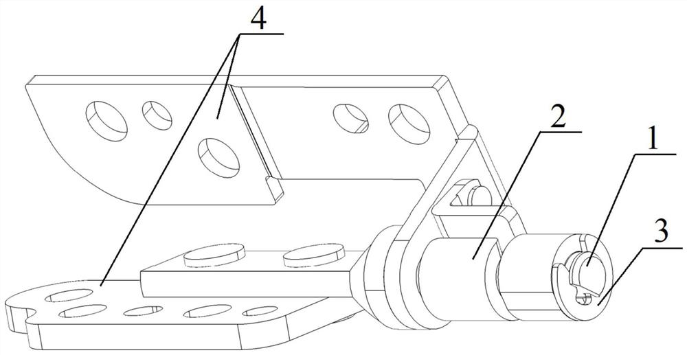
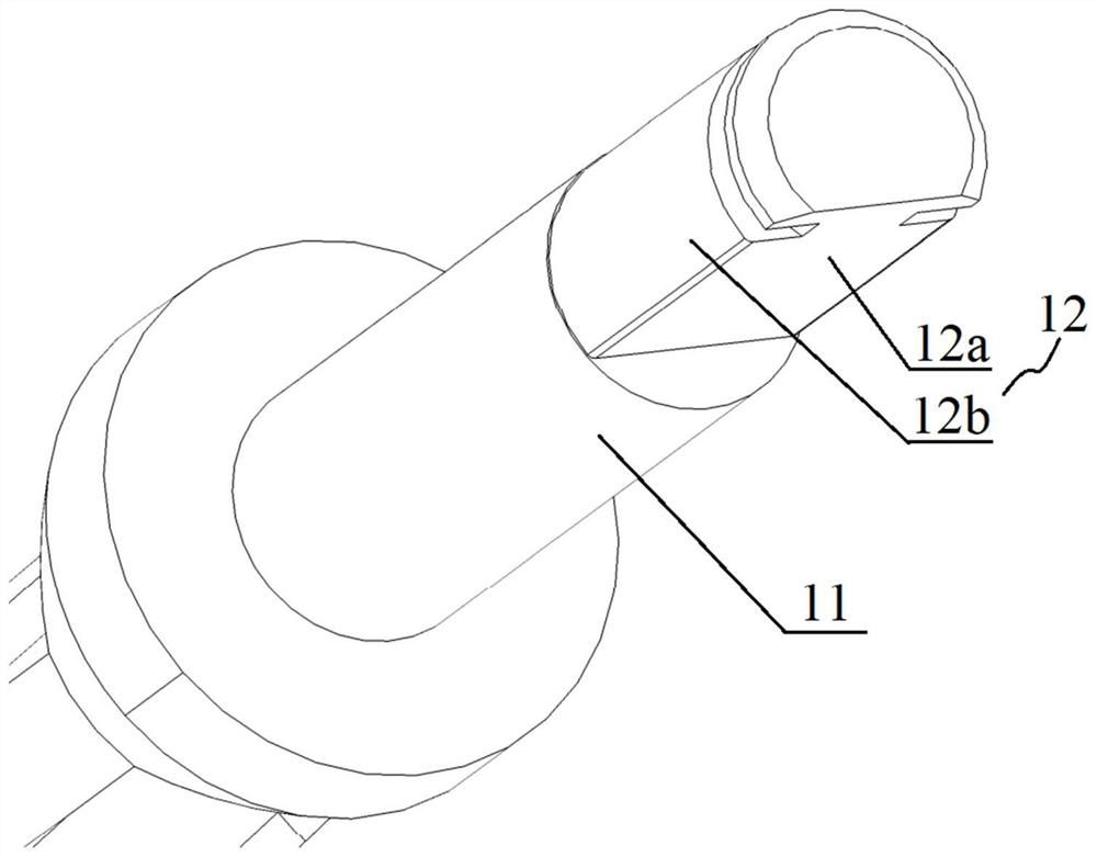
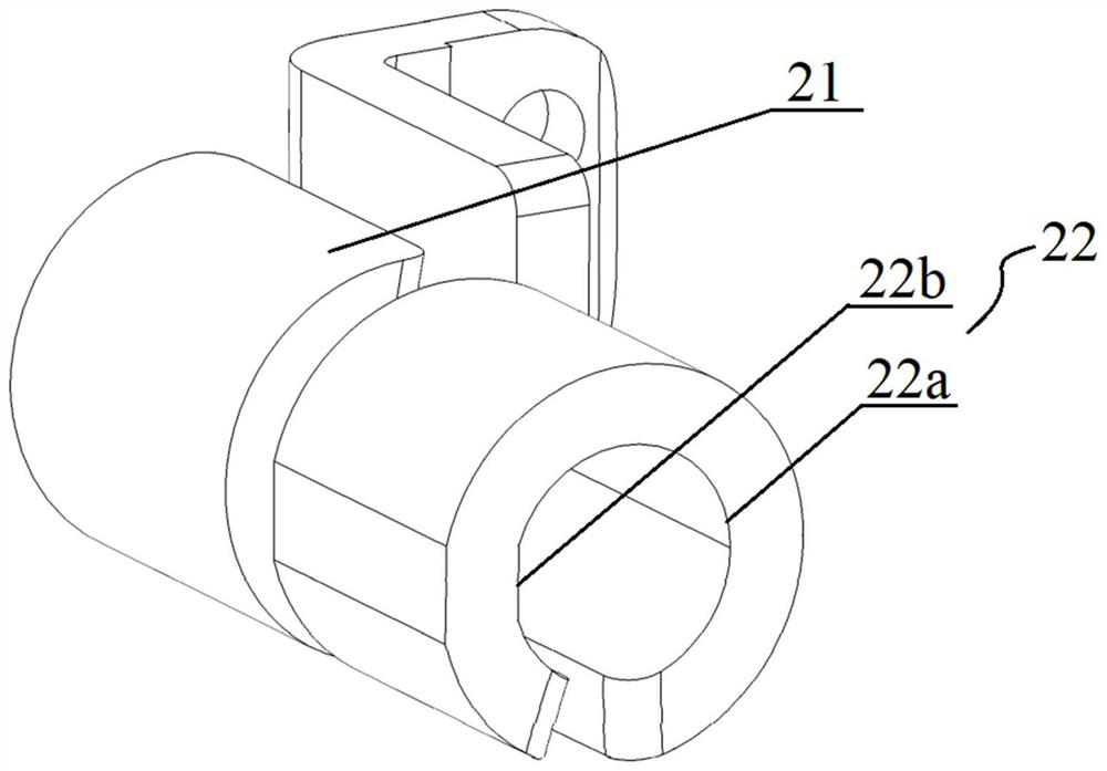
[0037] This embodiment provides a shaft mechanism, such as Figure 1-Figure 3 As shown, the rotating shaft mechanism includes: a rotating shaft bearing 1 and a torsion member 2 . Wherein, the rotating shaft bearing 1 includes a first bearing portion 11 and a second bearing portion 12, and the radius of the second bearing portion 12 is smaller than the radius of the first bearing portion 11; the rotating shaft bearing 1 is rotatably arranged in the torsion member 2, and the torsion member 2 includes a first torsion portion 21 surrounding the first bearing portion 11 and a second torsion portion 22 surrounding the second bearing portion 12, and the second torsion portion 22 includes a second avoidance portion 22a and a second braking portion 22b; the first The torsion portion 21 abuts against the first bearing portion 11 to generate a torsion force, and the second braking portion 22b abuts to the first braking portion 12b to generate a torsion force.

[0038] In this embodiment...

Embodiment 2

[0053] This embodiment provides an electronic device, which includes a first body, a second body, and the shaft mechanism described in Embodiment 1 above, the first body and the second body are connected to the shaft bearing 1 and the torsion member 2 respectively .

[0054] Such as figure 1 , Figure 5 and Figure 6 As shown, a body mounting part 4 is fixedly connected to the torsion part, and the second body is connected to the torsion part 2 through the body mounting part 4. Of course, the body mounting part 4 can also be directly integrally connected with the torsion part 2, but compared to this In the case of integral molding, by fixing a body mounting part 4 on the torsion member 2 and connecting the second body with the torsion part 2 through the body mounting part 4, the body mounting part 4 can exist independently from the torsion part 2, Thereby the thickness of above-mentioned machine body mounting part 4 can not be restricted by torsion part 2, or while guaranteei...


PUM


Abstract

The invention discloses a rotating shaft structure and electronic equipment, wherein the rotating shaft structure comprises a rotating shaft bearing and a torsion piece. The rotating shaft bearing comprises a first bearing part and a second bearing part, and the radius of the second bearing part is smaller than the radius of the first bearing part; the second bearing part comprises a first avoiding part and a first braking part; the rotating shaft bearing is rotatably arranged in the torsion piece, the torsion piece comprises a first torsion part surrounding the first bearing part and a second torsion part surrounding the second bearing part, and the second torsion part comprises a second avoiding part and a second braking part; and the first torsion part abuts against the first bearing part and generates torsion, and the second braking part abuts against the first brake part and generates torsion. According to the rotating shaft structure, the torsion of corresponding electronic equipment is small when the opening and closing angle is small, so that the force required to be applied by a user is small, and use by the user is facilitated; and when the opening and closing angle is large, the torsion is large, the effect of positioning a machine body can be achieved, and the situation that the machine body freely falls back is prevented.

Description

technical field [0001] The invention relates to the technical field of electronic equipment, in particular to a rotating shaft mechanism and an electronic equipment. Background technique [0002] The hinge, also known as the hinge, is a connecting element that can provide relative rotation. It is mainly used between the display part and the base part of electronic equipment. At present, it is widely used in various digital products and electronic equipment, such as notebook computers. 1. Computer, through the relative rotation function provided by the rotating shaft, the opening and closing, rotation positioning and self-closing functions between the display screen part and the base part of the notebook computer etc. are realized. [0003] In the prior art, for the adjustment of the torque of the rotating shaft, the required torque is obtained by operating the locking tightness of the fixing part or the nut, which is inconvenient to operate. At the same time, if the degree o...

Claims


Application Information

Patent Timeline
Patent Type & Authority Applications(China)
IPC IPC(8): F16C11/04F16C11/10
CPCF16C11/04F16C11/10
Inventor 司林生
Owner KUNSHAN VOSO HINGE ELECTRONICS TECH
Learn More