Horizontal table top capable of switching multiple stations and horizontal vibration testing machine

A vibration test and multi-station technology, which is applied in vibration test, machine/structural component test, measuring device, etc., can solve the problem that the horizontal platform cannot realize multi-directional test, etc., so as to save test man-hour cost and have strong versatility , the effect of improving test efficiency

Pending Publication Date: 2021-07-13
SUZHOU SUSHI TESTING INSTR CO LTD
2 Cites 0 Cited by

AI-Extracted Technical Summary

Problems solved by technology

[0004] The purpose of the present invention is to provide a multi-station switchable horizontal platf...

Method used

[0037] By arranging a plurality of slide rail segments 211, the installation difficulty of the slide rail 21 can be reduced, and by a...

Abstract

The invention provides a multi-station switchable horizontal table top, which is used for fixing a test piece for testing, and comprises a table top body provided with a circular mounting groove, a slide rail assembly fixed in the mounting groove, and a mounting table top arranged on the slide rail assembly; wherein the sliding rail assembly comprises an annular sliding rail and a plurality of sliding blocks arranged on the sliding rail, the sliding rail is fixedly connected with the table top body, the sliding blocks are arranged in a sliding mode relative to the sliding rail, and the installation table top and the sliding blocks are fixedly arranged so that the installation table top can rotate along the sliding rail. According to the horizontal table top capable of switching multiple stations and the horizontal vibration testing machine, multiple times of disassembly, hoisting and installation are not needed, the testing time cost is saved, the testing period is shortened, and the testing efficiency is improved; in the invention, the horizontal table top capable of switching the multiple stations is simple in structure and high in universality, and tests can be carried out at multiple positions in the same plane.

Application Domain

Technology Topic

Image

  • Horizontal table top capable of switching multiple stations and horizontal vibration testing machine
  • Horizontal table top capable of switching multiple stations and horizontal vibration testing machine
  • Horizontal table top capable of switching multiple stations and horizontal vibration testing machine

Examples

  • Experimental program(1)

Example Embodiment

[0024] The technical solutions of the present invention will be described below in conjunction with the drawings, as will be described, as described herein is an embodiment of the invention, not all of the embodiments. Based on the embodiments of the present invention, there are all other embodiments obtained without making creative labor without making creative labor premises.
[0025] In the description of the invention, it is to be described in the terms "center", "upper", "lower", "left", "right", "vertical", "horizontal", "within", "outside", etc. The orientation or positional relationship indicated is based on the orientation or positional relationship shown in the drawings, is merely intended to describe the present invention and simplified description, rather than indicating or implying that the device or component must have a specific orientation. Construct and operation, so it is not understood to be the limitation of the invention. Moreover, the term "first", "second", "third" is only used to describe purposes, and cannot be understood as an indication or implies relative importance.
[0026] In the description of the present invention, it is to be described in that, unless otherwise expressly specified and defined, the term "mount", "connected", "connection" should be broadly understood, for example, may be fixed connection, or detachable Connect, or integrate; it can be mechanical connection, or electrical connection; may be directly connected, or indirectly connected by an intermediate medium, which can be in the interior of the two elements. The specific meaning of the above terms in the present invention will be appreciated to those skilled in the art. Further, the technical features according to the different embodiments described below can be combined with each other as long as they do not constitute a collision between each other.
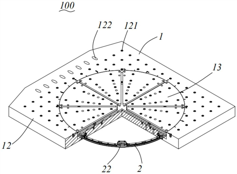
[0027] Such as Figure 1 to 8 As shown, the horizontal vibration testing machine of the present invention includes a multi-station switching horizontal table 100 and an electric vibrating table.
[0028] The electric vibrating table includes a dynamic ring and a fuel tank, and a connection hole is provided with a connecting hole to securely securing the aperture and the fuel tank. The aircraft is secured to the horizontal table, so that the water platform surface reciprocating can be driven. The tank is fixedly coupled to the horizontal surface 100 of the multi-station switching to provide guiding and support. Further, the connecting hole includes a mounting aperture 122 and a tank mounting aperture 132 that is fixed to the turning ring.
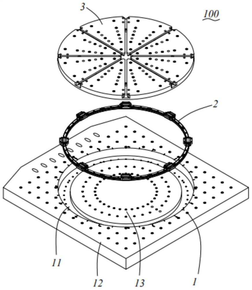
[0029] Such as Figure 1 to 2 As shown, the multi-station switching horizontal table surface 100 is used to fix the test piece for testing.
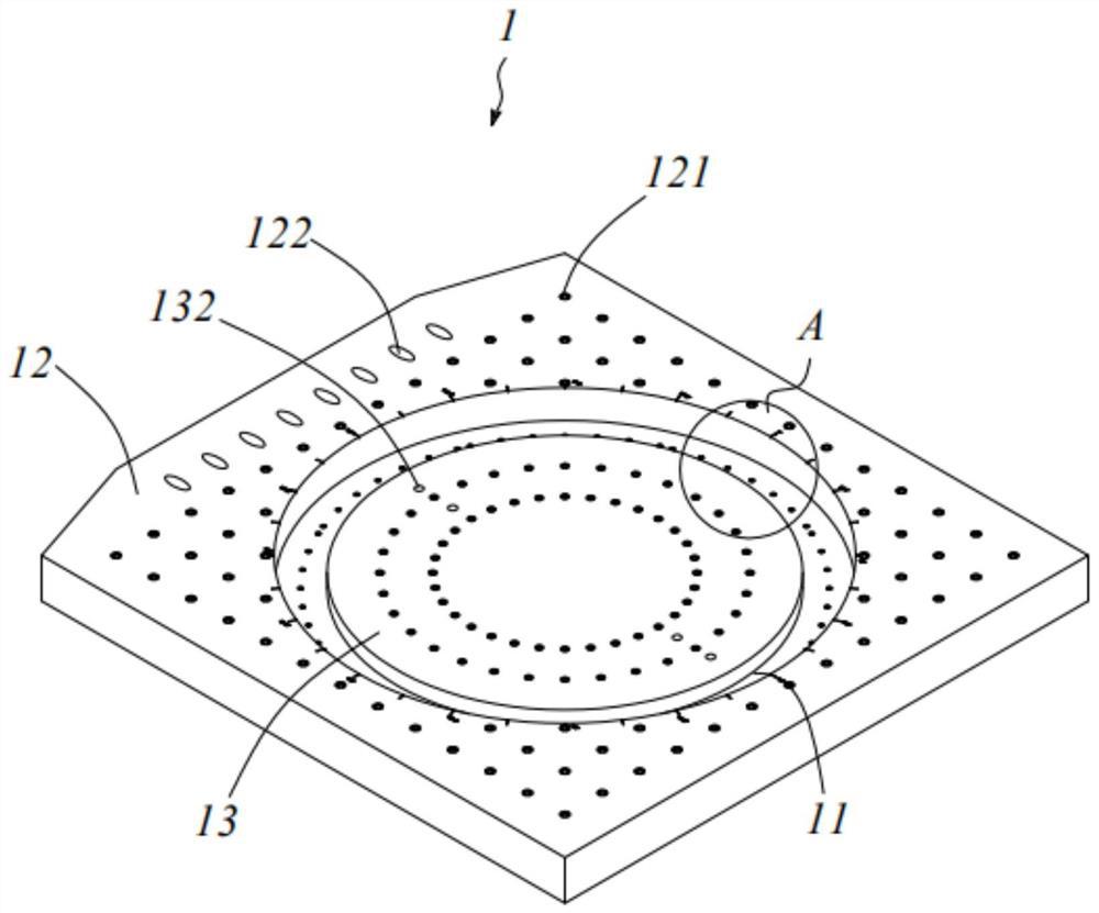
[0030] The multi-station switching horizontal table surface 100 includes a counteral body 1 having a circular mounting groove 11, which is fixed to the rail assembly 2 in the mounting groove 11, and is disposed on the mounting table surface on the rail assembly 2. 3.
[0031] Such as Figure 3 to 4 As shown, the table top body 1 includes an outer stage 12 disposed around the mounting groove 11, a mounting boss 13 that is upward from the mounting groove 11.
[0032] The outer stage 12 is provided with a secondary mounting threaded hole 121, a dynamic mounting aperture 122, a tie 123 disposed around the mounting groove 11. The auxiliary mounting threaded hole 121 is configured to assist the fixed test piece, and the mounting of the aperture 122 is mainly used to fix the connector on the moving ring, and the mounting of the open hole 122 is disposed outside. On the side of the table 12, set in parallel. The interval between the scale line 123 is equal to indicating the position of the mounting table 3.
[0033] A plurality of rotational positioning threaded holes 131 are opened on the mounting boss 13, and the fuel tank mounting aperture 132 is also opened on the mounting boss 13.
[0034] The outer stage 12 is provided with a slide mounting threaded hole 111 between the mounting boss 13, and the rail assembly 2 is fixedly coupled to the slide rail mounting threaded hole 111.
[0035] Such as Figure 5 to 6 As shown, the rail assembly 2 includes a circular slide rail 21, a plurality of slider 22 disposed on the rail 21. In this embodiment, the slide rail 21 is fixed to the table top body 1, the rail assembly 2 mounted between the outer stage 12 and the mounting boss 13. The slide rail 21 is fixedly coupled to the slide rail mounting threaded hole 111. The slider 22 is slidably disposed with respect to the slide rail 21, and is fixed to the mounting table 3.
[0036] In this embodiment, the rail 21 includes a plurality of slide segments 211, each of which is provided with a slider 22, and the distance between the two slide 22 is equal. The number of rail segments 211 and the slider 22 is eight. The mounting table 3 is fixed to the slider 22 such that the mounting table 3 can be rotatable along the rail 21.
[0037] By providing a plurality of slide segments 211, it can reduce the installation difficulty of the rail 21, by providing a plurality of slider 22, the plane of the mounting table 3 can be maintained and stabilized during the test process.
[0038] Such as Figure 7 to 8 As shown, the mounting table face 3 includes a rotation plate 31, a plurality of T-slots 32 open on the rotating plate 31, provided in the T-groove 32 to secure the T-nut 33 of the test piece.
[0039] The rotating plate 31 is opened to secure the inlet hole 311, the slider mounting threaded hole 313, the guide port 315, and an indication mark 314.
[0040]The slider fixed counter hole 311 is disposed at the edge of the rotation plate 31, each of which is provided with four of the slider fixing aperture 311. The rotating plate 31 is fixed through the slider through the slider to fix the slider 22, thereby achieving the effect of fixing the slider 22 and the transfer plate 31 such that the transfer plate 31 can be mounted relative to the mounting. The plane 3 is rotated.
[0041] The rotary positioning aperture 312 corresponds to the rotational positioning threaded hole 131 to rotate in the rotation 31, and is attached to the screw 31 and the mounting boss 13 securely. The rotation positioning aperture 312 is distributed over a plurality of positions on the rotation plate 31.
[0042] The time mounting threaded hole is used to secure the test piece on the transfer plate 31, and when the transfer plate 31 is rotated to the set position, the auxiliary mounting threaded hole of the test piece and the outer stage 12 121 is fixed so that the test piece is fixed to the horizontal table 100 of the multi-station switching.
[0043] In this embodiment, the indication flag 314 is an arrow, so that the angle of rotation can be controlled using the opposite position of the arrow and the tick line 123. The arrow is disposed within the T-slot 32.
[0044] The T-groove 32 extends radially along the rotation plate 31 and the cross section is pour T-type to prevent the T-type nut 33 from detaching.
[0045] The guiding port 315 is disposed at one end of the rotation plate 31 away from the center and communicated with the T-type groove 32 to mount the T-type nut 33 into the T-slot 32. Further, the test piece mounting threaded hole 313 is disposed on both sides of the T-slot 32.
[0046] The test piece is fixed to the T type nut 33 to facilitate the radial movement of the rotation plate 31, controlled in the radial direction.
[0047] The method of use of the horizontal vibration test machine of the present invention is as follows: The diameter table is fixed to the horizontal table 100 of the multi-station switching, and the test piece is fixed to the T-type nut 33; the T-type nut 33 is moved to place the The test piece moves to a suitable position, and the rotation positioning counter 312 is connected to the rotation positioning the threaded hole 131 by the screw to position the rotating plate 31 and the mounting boss 13; through the screw Fixed with the countertop body 1 and the mounting table surface 3; followed by test; when the test is required to replace other directions or positions, only the screws between the test piece and the countertop body 1 and the mounting surface 3 are required, and the transfer plate 31 is required. And mounting the screws for positioning, then move the test piece; re-tighten the screw after reaching the preset position, and do not have to disassemble, hoist and install, save the cost of test work, shorten the test cycle, Improve test efficiency.
[0048] The multi-station switching horizontal table 100 and horizontal vibration test machine of the present invention do not have to be disassembled, hoisting and installed, saving test work time, shortening the test cycle, and improving test efficiency; It can be clearly known that the relative position of the test piece; the multi-station switching of the present invention, the horizontal surface 100 and the horizontal vibration test machine, simple structure, strong versatility, and realize multiple locations in the same plane. Test.
[0049] The various technical features of the above embodiments may be arbitrarily combined, in order to make the description, the possible combinations of various technical features in the above embodiments are not described, however, as long as the combination of these technical features does not have contradictions, It should be considered as the scope of this specification.
[0050] The above embodiments are merely expressed in several embodiments of the invention, which are more specific and detailed, but is not to be construed as limiting the invention. It should be noted that for ordinary skill in the art, several deformations and improvements can be made without departing from the concept of the present invention, which belongs to the scope of the present invention. Therefore, the scope of the scope of the invention should be taken as the appended claims.

PUM

no PUM

Description & Claims & Application Information

We can also present the details of the Description, Claims and Application information to help users get a comprehensive understanding of the technical details of the patent, such as background art, summary of invention, brief description of drawings, description of embodiments, and other original content. On the other hand, users can also determine the specific scope of protection of the technology through the list of claims; as well as understand the changes in the life cycle of the technology with the presentation of the patent timeline. Login to view more.

Similar technology patents

Durability test device for wiring harness of automobile chassis

InactiveCN107202699AShorten the test cycleReduce the difficulty of test operationVehicle testingAutomotive engineeringRolling chassis
Owner:广电计量检测(武汉)有限公司 +1

NAS test system, method and computer-readable storage medium

InactiveCN109471784AReduced test accuracyShorten the test cycleHardware monitoringComputer hardwareTest script
Owner:ZHENGZHOU YUNHAI INFORMATION TECH CO LTD

Classification and recommendation of technical efficacy words

Why Eureka
Try Eureka