Low-power-consumption target monitoring device, method and system
A monitoring device and low-power technology, applied in the field of smart devices, can solve the problems of high power consumption of radar sensors and PIR sensor modules, and no solutions are proposed, and achieve the effect of simple and easy-to-understand purposes and advantages.
- Summary
- Abstract
- Description
- Claims
- Application Information
AI Technical Summary
Problems solved by technology
Method used
Image

Examples
specific Embodiment 1
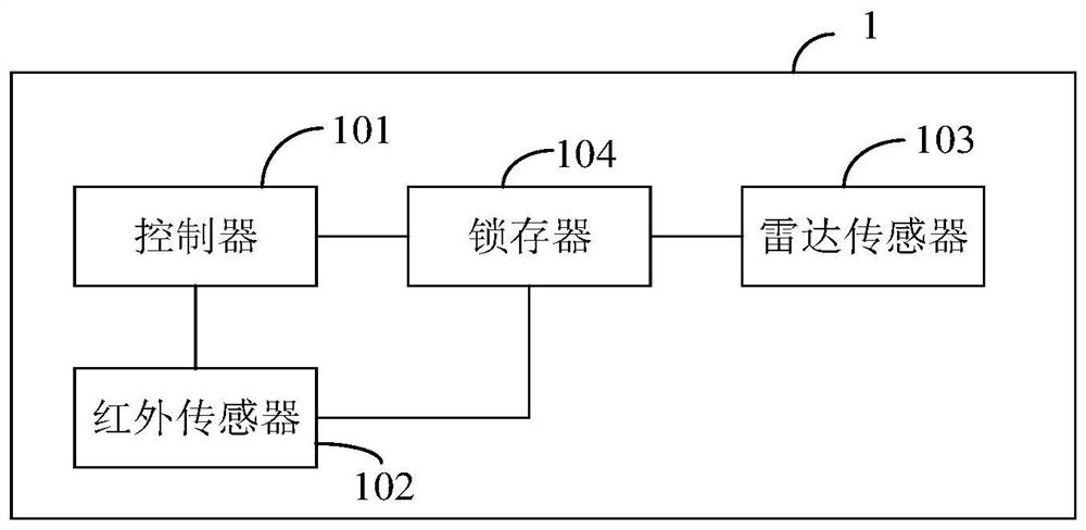
[0079] This embodiment provides a low power consumption target monitoring device. figure 1 is a structural block diagram of a low-power target monitoring device according to an embodiment of the present application. Those skilled in the art can understand that, figure 1 The structure of the low-power target monitoring device shown in the above does not constitute a limitation to the low-power target monitoring device, and may include more or less components than shown in the figure, or combine some components, or arrange different components.
[0080] Combine below figure 1 A specific introduction to each component module of the low-power target monitoring device:
[0081] The infrared sensor 102 is used to monitor the target object within the detection range and send a first monitoring signal;
[0082]The radar sensor 103 is used to monitor the target object within the detection range and send a second monitoring signal. It is worth noting that the infrared sensor 102 moni...
specific Embodiment 2
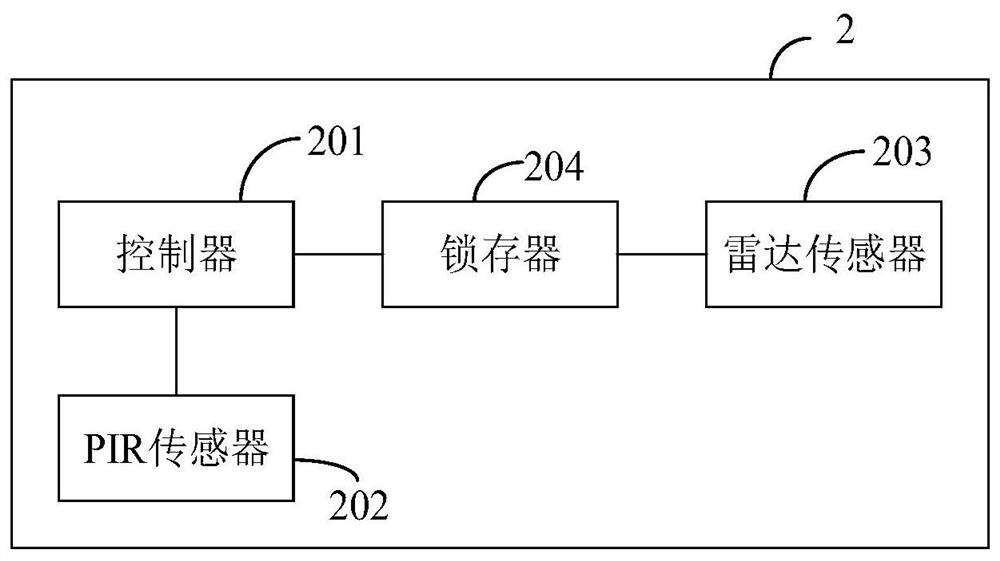
[0091] image 3 It is a structural block diagram of another low-power target monitoring device according to an embodiment of the present application. refer to image 3 , the device of this embodiment at least includes:
[0092] The PIR sensor 202 is used to monitor the target object within the detection range and send out the first monitoring signal. Compared with the traditional active infrared sensor, the PIR sensor 202 does not emit any type of radiation itself, and has good concealment and low device power consumption. Small and cheap;
[0093] The radar sensor 203 is used to monitor the target object within the detection range and send a second monitoring signal, wherein the radar sensor 203 monitors the target object and enters a sleep state after sending the second monitoring signal;
[0094] The latch 204 is electrically connected to the radar sensor 203 and is used to receive the second monitoring signal and record it as high and low level signals. The latch 204 i...
specific Embodiment 3
[0102] Based on the low-power consumption target monitoring device in the first specific embodiment, this embodiment also provides a control method of the low-power consumption target monitoring device. Figure 5 is a flow chart of a control method of a low-power target monitoring device according to an embodiment of the present application, such as Figure 5 As shown, the process includes the following steps:
[0103] Infrared sensor monitoring step S301, the infrared sensor monitors the target object and sends out a first monitoring signal. If the controller judges that the target object is detected according to the first monitoring signal or the first level signal, it fails to detect the target object within the first preset time threshold range. If the target object is detected again, enter the radar sensor monitoring step S302, otherwise repeat this step;
[0104] Radar sensor monitoring step S302, the radar sensor monitors and sends a second monitoring signal, if the co...
PUM
 Abstract
Description
Claims
Application Information
 - R&D
- Intellectual Property
- Life Sciences
- Materials
- Tech Scout
- Unparalleled Data Quality
- Higher Quality Content
- 60% Fewer Hallucinations
Browse by: Latest US Patents, China's latest patents, Technical Efficacy Thesaurus, Application Domain, Technology Topic, Popular Technical Reports.
© 2025 PatSnap. All rights reserved.Legal|Privacy policy|Modern Slavery Act Transparency Statement|Sitemap|About US| Contact US: help@patsnap.com