
Optimization system and method for cross-well electromagnetic remote detection transceiving antenna

A technology for transmitting and receiving antennas and remote detection, applied in the field of geophysical exploration and development, can solve the problems of weak magnetic field signal, insignificant amplitude change, insufficient formation information, etc., and achieve the effects of increasing input current, increasing detection distance, and widening optional range.

Active Publication Date: 2021-07-13
UNIV OF ELECTRONICS SCI & TECH OF CHINA
View PDF6 Cites 2 Cited by
  • Summary
  • Abstract
  • Description
  • Claims
  • Application Information

AI Technical Summary

Problems solved by technology

In traditional cross-well electromagnetic logging, the antenna design mostly uses a single transmitting and receiving coil to be placed in two or more wells for transmitting and receiving respectively. The magnetic field signal received by the detection receiving end is weak, the amplitude change is not obvious, the target is difficult to identify, the detection ability is weak, and the formation information obtained is insufficient, so it is impossible to image the interwell formation

Method used


Image

  • Optimization system and method for cross-well electromagnetic remote detection transceiving antenna
  • Optimization system and method for cross-well electromagnetic remote detection transceiving antenna
  • Optimization system and method for cross-well electromagnetic remote detection transceiving antenna

Examples


Embodiment 1

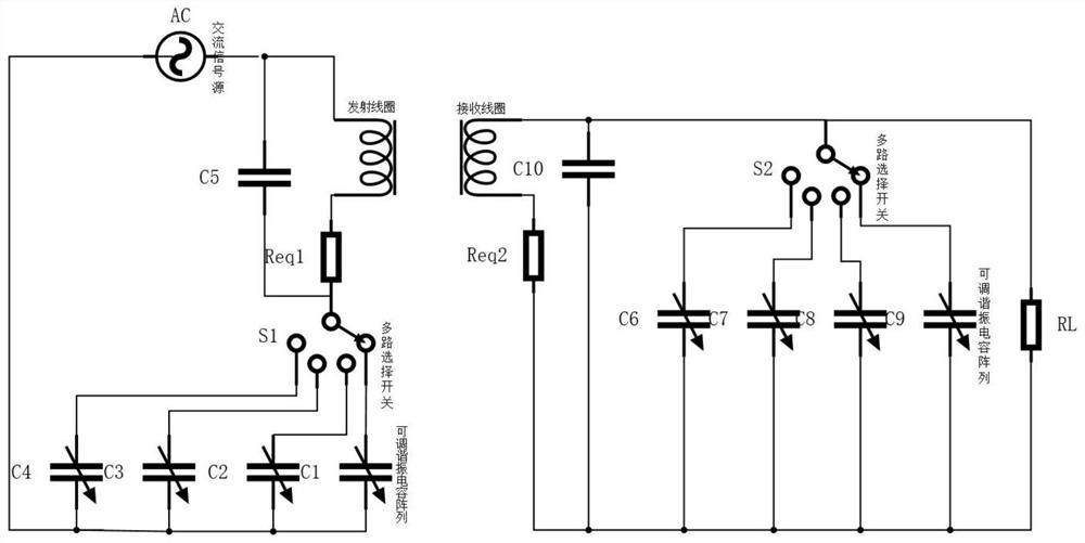
[0024] like figure 1 As shown, the present embodiment provides an optimized system for interwell electromagnetic remote detection transceiver antenna, which includes a transmitting antenna circuit and a receiving antenna circuit; the transmitting antenna circuit includes a transmitting coil L1, and the transmitting coil L1 is selected by the first multiplex The switch S1 is connected in series with the first tunable capacitor array; the receiving antenna circuit includes a receiving coil L2, and the receiving coil L2 is connected in parallel with the second tunable capacitor array through the second multiplex switch S2.

[0025] The first tunable capacitor array includes capacitors C1, C2, C3, and C4 with different withstand voltage values ​​and different capacitance values, and the second tunable capacitor array includes capacitors C6, C7, C8, and C9 with different withstand voltage values ​​and different capacitance values.

[0026] The transmitting coil L1 has an AC signal ...


PUM


Abstract

The invention relates to the technical field of geophysical exploration and development, in particular to an optimization system and method for a cross-well electromagnetic remote detection transceiving antenna. The system comprises a transmitting antenna circuit and a receiving antenna circuit. The transmitting antenna circuit comprises a transmitting coil L1, and the transmitting coil L1 is connected in series with a first tunable capacitor array through a first multiplexer switch S1; the receiving antenna circuit comprises a receiving coil L2, and the receiving coil L2 is connected in parallel with a second tunable capacitor array through a second multiplexer switch S2. According to the invention, the inter-well detection distance can be effectively increased, and the inter-well long-distance exploration and development capability is improved.

Description

technical field [0001] The invention relates to the technical field of geophysical exploration and development, in particular to an optimization system and method for an interwell electromagnetic remote detection transceiver antenna. Background technique [0002] With the mining of underground mineral resources, the depth of oil reservoir mineral resources on the surface is getting deeper and deeper. In traditional cross-well electromagnetic logging, the antenna design mostly uses a single transmitting and receiving coil to be placed in two or more wells for transmitting and receiving respectively. The magnetic field signal received by the detection receiving end is weak, the amplitude change is not obvious, the target is difficult to identify, the detection ability is weak, and the formation information obtained is insufficient, so it is impossible to image the interwell formation. The realization of cross-well electromagnetic remote detection not only needs to enhance the...

Claims


Application Information

Patent Timeline
Patent Type & Authority Applications(China)
IPC IPC(8): G01V3/12H01Q1/36
CPCG01V3/12H01Q1/36
Inventor 赵青程丽娜郭成
Owner UNIV OF ELECTRONICS SCI & TECH OF CHINA
Learn More