Heat dissipation device

A technology of heat dissipation equipment and heat dissipation plate, applied in the field of frequency conversion cabinets, can solve the problem of heat concentration and inability to spread, and achieve the effects of improving heat dissipation utilization rate, improving heat dissipation efficiency, and reducing temperature difference

Pending Publication Date: 2021-07-13
SHENZHEN INOVANCE TECH
View PDF0 Cites 0 Cited by
  • Summary
  • Abstract
  • Description
  • Claims
  • Application Information

AI Technical Summary

Problems solved by technology

[0003] The main purpose of the present invention is to provide a heat dissipation device, which aims to solve the problem of heat concentration and cannot be diffused during heat dissipation, and improve the heat dissipation utilization rate of the heat dissipation plate

Method used


Image

  • Heat dissipation device
  • Heat dissipation device
  • Heat dissipation device

Examples


Embodiment Construction

[0030] The following will clearly and completely describe the technical solutions in the embodiments of the present invention with reference to the accompanying drawings in the embodiments of the present invention. Obviously, the described embodiments are only part of the embodiments of the present invention, not all of them. Based on the embodiments of the present invention, all other embodiments obtained by persons of ordinary skill in the art without creative efforts fall within the protection scope of the present invention.

[0031] It should be noted that all directional indications (such as up, down, left, right, front, back...) in the embodiments of the present invention are only used to explain the relationship between the components in a certain posture (as shown in the accompanying drawings). Relative positional relationship, movement conditions, etc., if the specific posture changes, the directional indication will also change accordingly.

[0032] In the present in...


PUM


Abstract

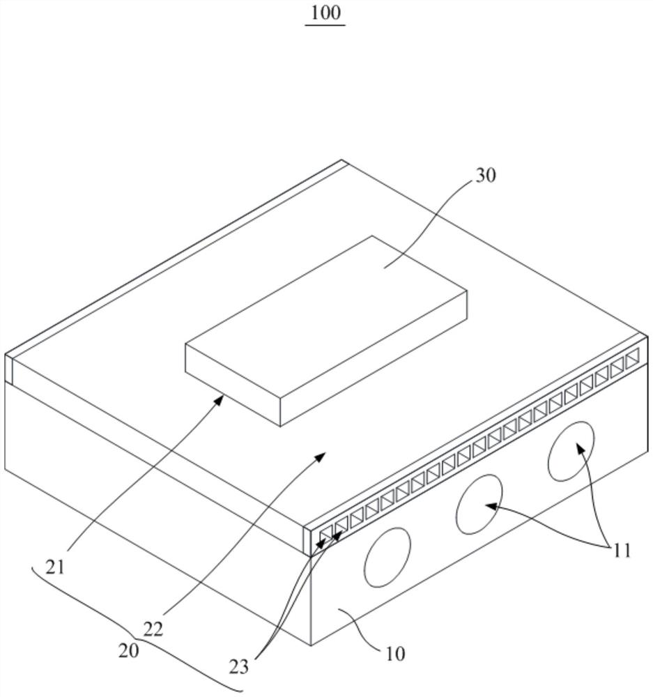
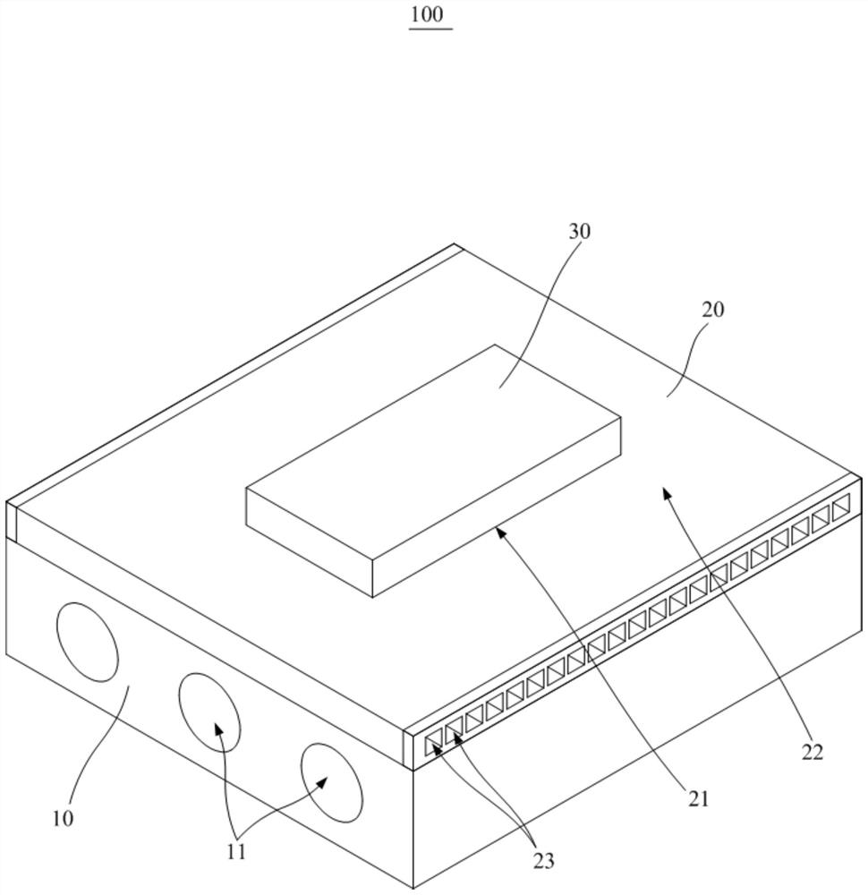
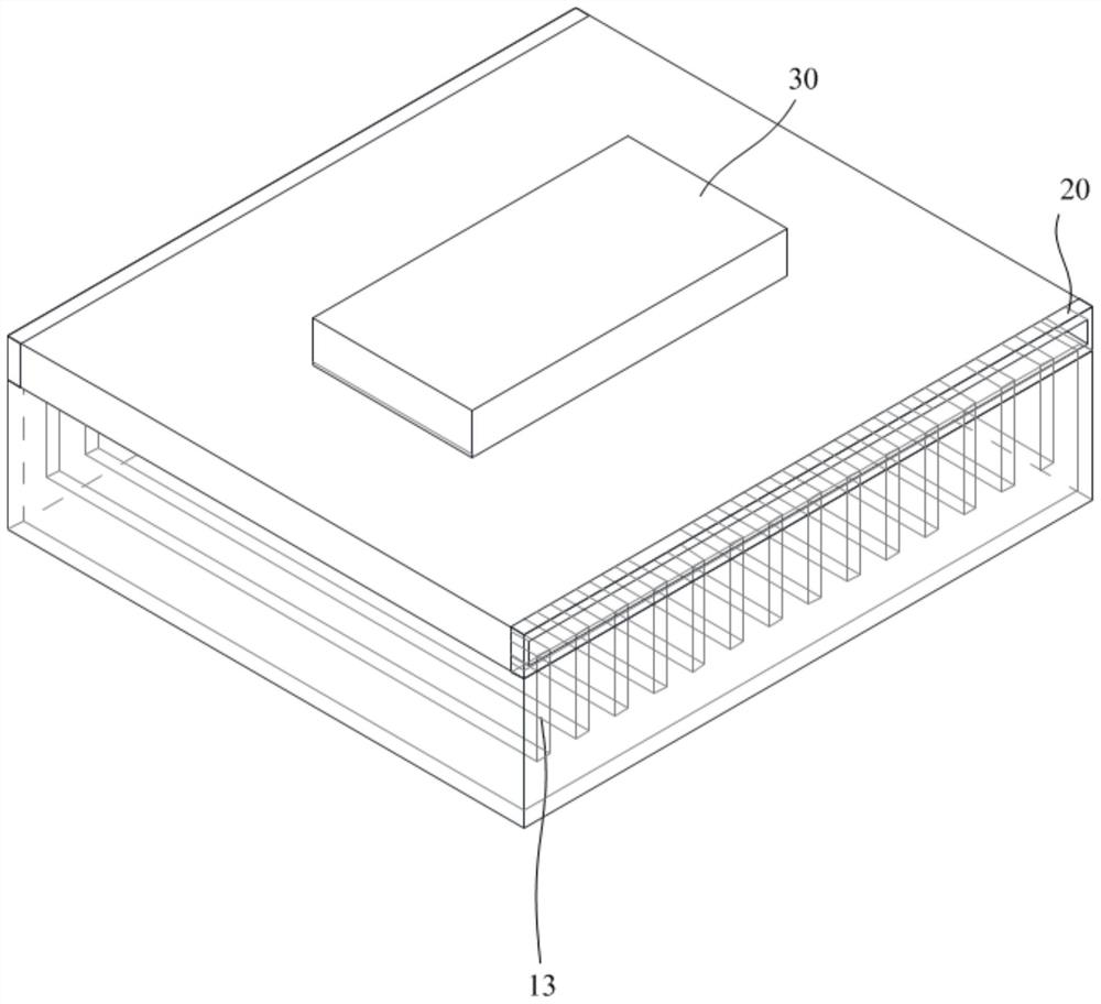
The invention discloses a heat dissipation device, which comprises a heat dissipation plate and a uniform temperature plate, and is characterized in that the heat dissipation plate is internally provided with a liquid cooling channel and/or heat dissipation fins; the first side of the uniform-temperature plate is attached to one side of the heat dissipation plate, the second side surface of the uniform-temperature plate is a heat source part mounting surface, a plurality of uniform-temperature channels are formed in the uniform-temperature plate, and the uniform-temperature channels are filled with phase change working media; a first area and a second area are formed on the uniform-temperature plate, the heat source piece is installed on the surface of the first area, and the uniform-temperature channel guides heat of the heat source piece from the first area to the second area. According to the technical scheme, the problem that heat is concentrated and cannot be diffused during heat dissipation is solved, and the heat dissipation utilization rate of the heat dissipation plate is increased.

Description

technical field [0001] The invention relates to the technical field of frequency conversion cabinets, in particular to a cooling device. Background technique [0002] In the field of heat dissipation, the radiator is mainly used to dissipate heat for devices with large heat loss, and quickly transfer the heat of the device to the heat sink to ensure that the device can work normally and stably. How to quickly transfer heat from the radiator to the ambient heat sink is very important. Commonly used liquid-cooled plate radiators usually increase the flow channel at the radiator base plate, so that the cooling fluid flows through the liquid-cooled plate below the device, carrying the cooling heat of the electronic device to reduce the temperature of the electronic device. However, when a liquid-cooled plate radiator is currently used, the temperature of the liquid-cooled plate near the installation position of the electronic device is higher, and the temperature in other place...

Claims


Application Information

Patent Timeline
Patent Type & Authority Applications(China)
IPC IPC(8): H05K7/20
CPCH05K7/20327H05K7/20336H05K7/20936
Inventor 吴国强柏子平严运锋王能飞邱宏杰
Owner SHENZHEN INOVANCE TECH
Why Eureka
Try Eureka