
Clamp for transferring metal part

A technology of metal parts and fixtures, which is applied in the field of metal parts transfer fixtures, can solve the problems of unreasonable design, single and single function of fixtures, etc., and achieve the effect of convenient clamping

Pending Publication Date: 2021-07-16
ANHUI UNIVERSITY OF TECHNOLOGY AND SCIENCE
View PDF0 Cites 1 Cited by
  • Summary
  • Abstract
  • Description
  • Claims
  • Application Information

AI Technical Summary

Problems solved by technology

[0004] The object of the present invention is to provide a clamp for transferring metal parts to solve the above-mentioned background technology. The existing clamp itself is controlled by a single cylinder or motor, and the functions that can be realized are also more single. However, the metal parts are in different places. When transferring between processes, it is often necessary to adjust the height or angle of the metal parts to meet the requirements of different processing positions. When the existing fixtures realize the above functions, they need to use other driving structures besides the fixtures. The problem of unreasonable design and single fixture function

Method used


Image

  • Clamp for transferring metal part
  • Clamp for transferring metal part
  • Clamp for transferring metal part

Examples


Embodiment Construction

[0026] The following will clearly and completely describe the technical solutions in the embodiments of the present invention with reference to the accompanying drawings in the embodiments of the present invention. Obviously, the described embodiments are only some, not all, embodiments of the present invention. Based on the embodiments of the present invention, all other embodiments obtained by persons of ordinary skill in the art without making creative efforts belong to the protection scope of the present invention.

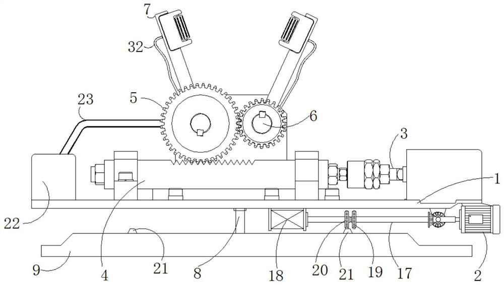
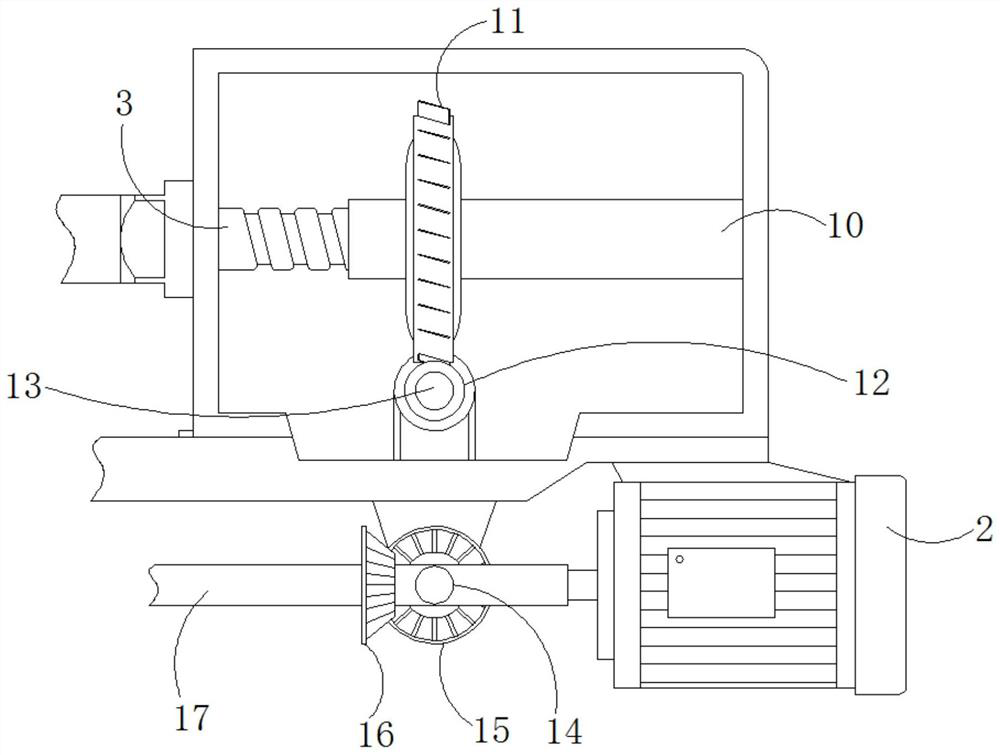
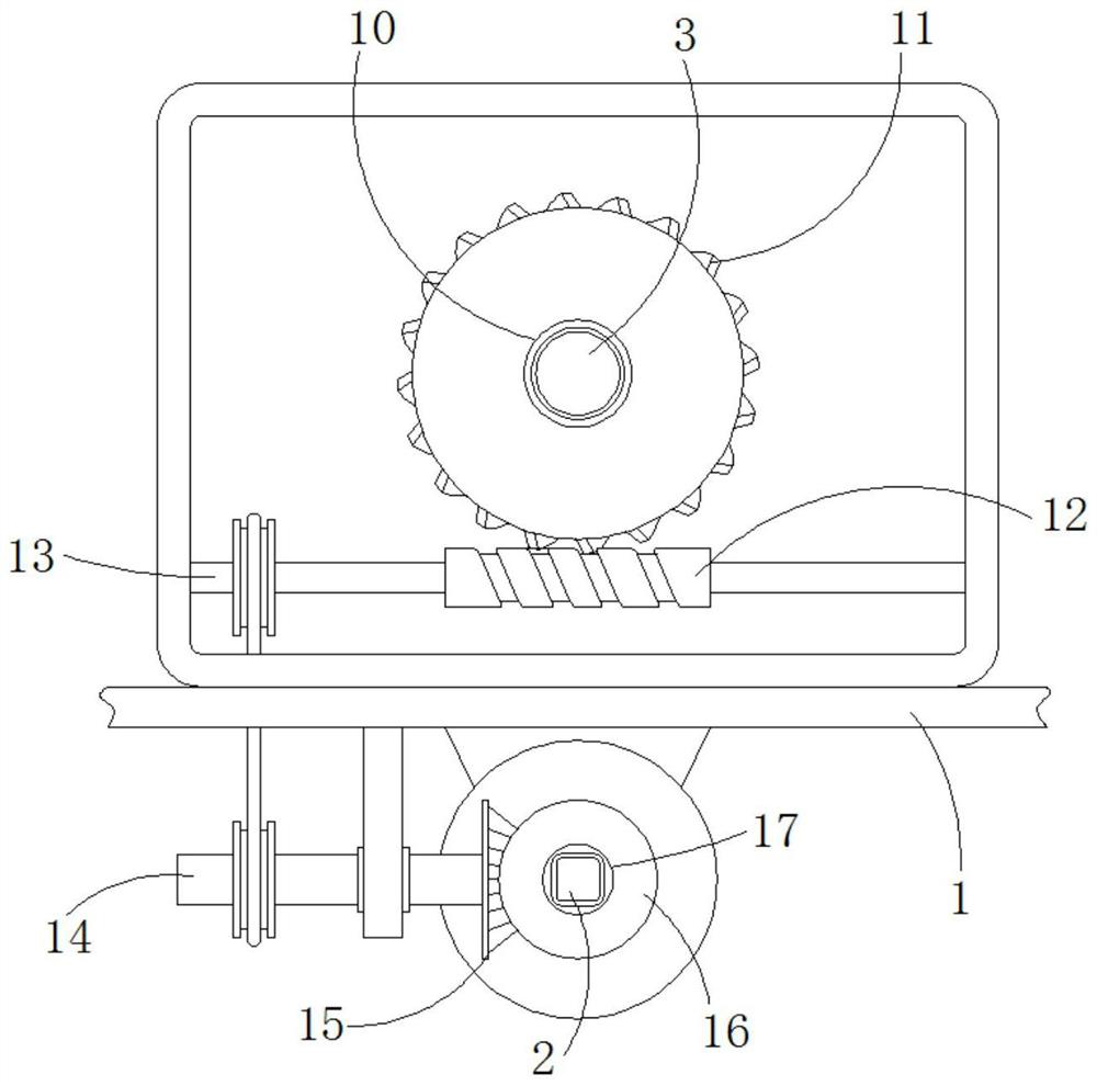
[0027] see Figure 1-6 , the present invention provides a technical solution: a jig for transferring metal parts, including a base 1, a motor 2, a cross bar 3, an alveolar plate 4, a transmission gear 5, a drive shaft 6, a jig plate 7, a rotating rod 8, a base Seat 9, horizontal cylinder 10, worm gear 11, worm screw 12, rotating shaft 13, transmission shaft 14, first bevel gear 15, second bevel gear 16, sleeve 17, electric telescopic rod 18, first vertical gea...


PUM


Abstract

The invention discloses a clamp for transferring a metal part. The clamp comprises a base, an electromotor, a tooth groove plate, transmission gears and driving shafts, the electromotor is installed below the base and used for driving a transverse rod to move horizontally, the transverse rod is horizontally installed on the upper end face of the base in a sliding mode, the two transmission gears are installed on the left driving shaft and the right driving shaft respectively, the driving shafts are horizontally and rotationally installed above the base, and the driving shafts are fixedly connected with the tail end of a clamp plate. According to the clamp for transferring the metal part, a clamp mechanism is redesigned, operation of the same motor is utilized, on the basis that the basic function that the clamp clamps a workpiece is complete, convenient adjustment can be carried out on the angle of the clamped workpiece, the two functions do not influence each other, meanwhile, the structure of the clamp plate in the clamp is redesigned, and air flow is used as power to synchronously achieve adjustment on the height of the workpiece and removal of chippings and dust after surface machining.

Description

technical field [0001] The invention relates to the technical field of metal piece processing, in particular to a jig for metal piece transfer. Background technique [0002] During the processing of metal parts, it is necessary to use fixtures to transfer them to different processes. Most of the fixtures are simple symmetrically distributed jaw mechanisms, which use cylinders or motors as the driving force to make the jaws rotate in different directions synchronously. The clamping of the workpiece is fixed, but the existing similar fixtures still have the following problems in actual use: [0003] The existing fixture itself is controlled by a single cylinder or motor, and the functions that can be realized are also more single. However, when metal parts are transferred between different processes, it is often necessary to adjust the height or angle of the metal parts to adapt to different processes. However, when the existing fixtures realize the above functions, other dri...

Claims


Application Information

Patent Timeline
Patent Type & Authority Applications(China)
IPC IPC(8): B23Q7/04
CPCB23Q7/043B23Q7/045
Inventor 李向利王幼民李昕健李军朱兆哲张晖龚逸凡王国清段维维
Owner ANHUI UNIVERSITY OF TECHNOLOGY AND SCIENCE
Learn More