Double-arm yarn guide hook

A yarn guide and double-arm technology is applied in the field of yarn guides, which can solve the problems of difficult surface treatment, redundant action, time-consuming and laborious, and inconvenient processing, so as to reduce the workload of check-in vehicles, improve the stand capacity, and simplify the operation. Effect

Inactive Publication Date: 2021-07-16
倪远
View PDF1 Cites 0 Cited by
  • Summary
  • Abstract
  • Description
  • Claims
  • Application Information

AI Technical Summary

Problems solved by technology

The sliver guiding operation of the ordinary yarn guide hook is a relatively large curved movement of up, down, left, and right circles. The operation process is redundant, time-consuming and labor-intensive, relatively labor-intensive, and the jointing efficiency is low.
[0003] The Chinese patent application number is 201811602561.3 The patent application for an open yarn guide hook, which proposes an open yarn guide hook structure that facilitates the entry of yarn sliver, but its special structure makes it inconvenient to process, difficult to process the surface, and expensive to manufacture. high
Due to the incomplete closure of the yarn guide hole in the circumferential direction, there are jumping points in the rotational movement of the yarn, which leads to additional fluctuations in spinning tension and increases the probability of additional spinning ends
At the same time, the two end structures of the yarn guide and the yarn catcher are not only low in strength but also poor in safety, so it is difficult to enter industrial applications

Method used


Image

  • Double-arm yarn guide hook
  • Double-arm yarn guide hook
  • Double-arm yarn guide hook

Examples


Embodiment 1

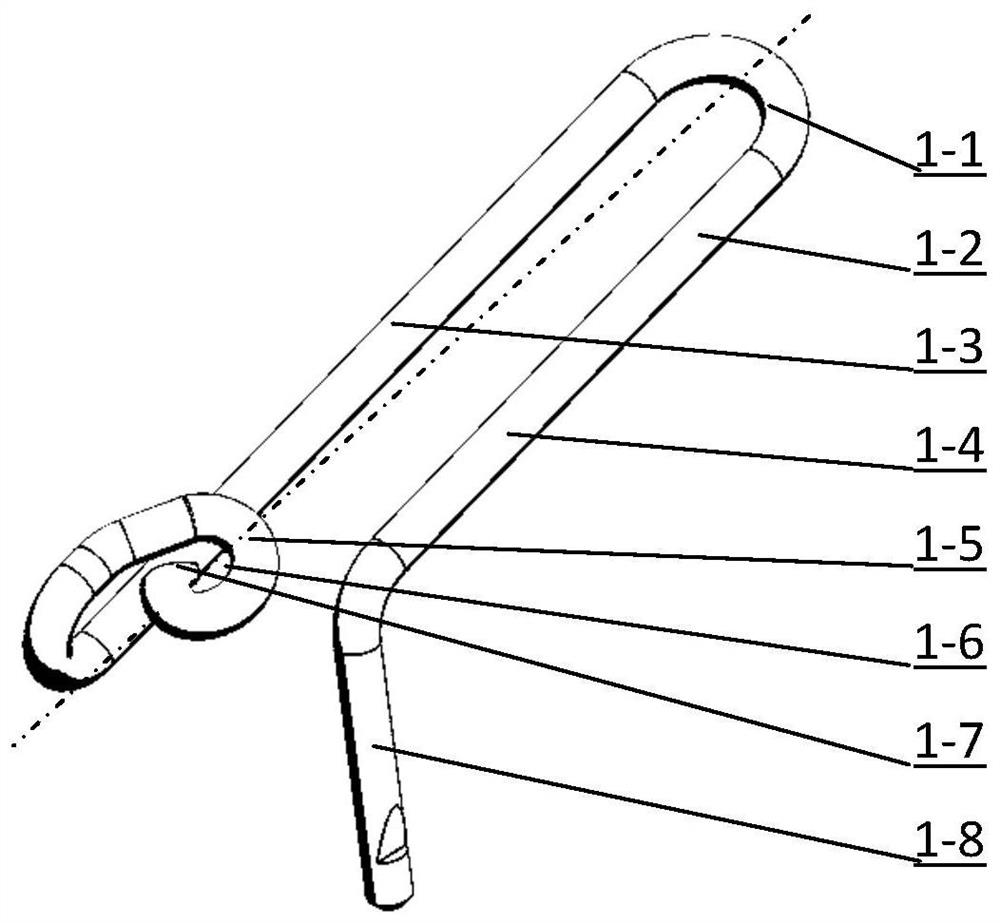
[0021] Example 1 see figure 1 , the two arms of the U-shaped tail part 1-1 and the fixed part 1-2 are the yarn guide arm 1-3 and the yarn capture arm 1-4, which respectively extend the yarn guide 1-5 and the yarn capture device 1-8, and the guide The yarn arm 1-3 is bent from bottom to top, and then the center line of the guide yarn hook is bent to form a spiral annular yarn guide 1-5 with a yarn guide hole 1-6 in the center, and the end of the yarn guide 1-7 is bent downward Fold, yarn catcher 1-8 catches yarn end downward.

Embodiment 2

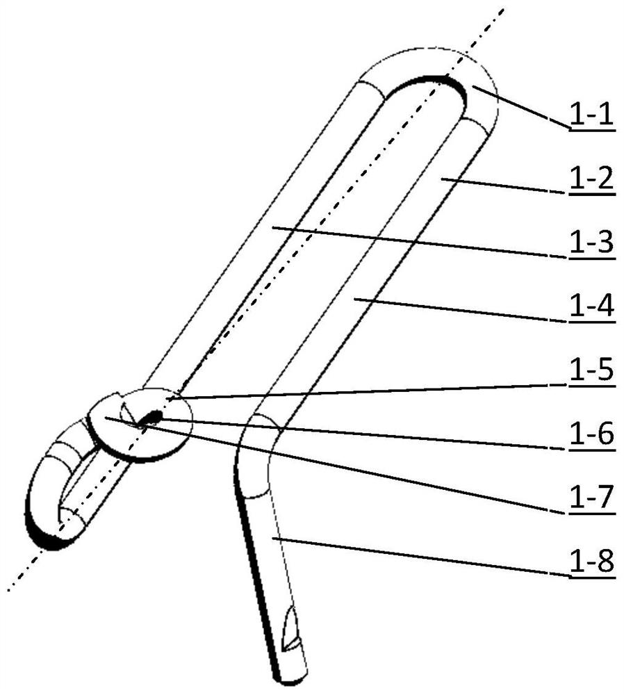
[0022] Example 2 see figure 2 , the two arms of the U-shaped tail part 2-1 and the fixed part 2-2 are the yarn guide arm 2-3 and the yarn capture arm 2-4, which respectively extend the yarn guide 2-5 and the yarn capture device 2-8, and the guide The yarn arm 2-3 is bent from bottom to top, and then the center line of the guide yarn hook is bent to form a spiral annular yarn guide 2-5 with a yarn guide hole 2-6 in the center, and the end of the yarn guide 2-7 is bent upward , Yarn catcher 2-8 catches yarn end downward.

Embodiment 3

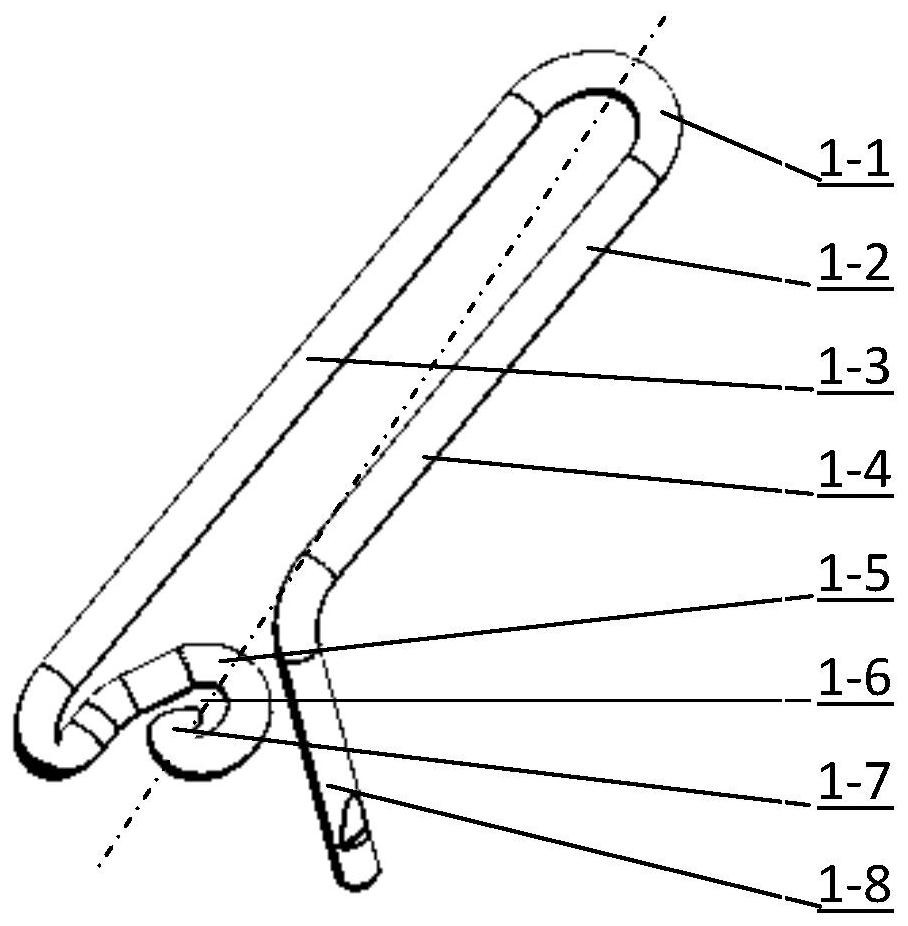
[0023] Example 3 see image 3 , the two arms of the U-shaped tail part 3-1 and the fixed part 3-2 are the yarn guide arm 3-3 and the yarn capture arm 3-4, which respectively extend the yarn guide 3-5 and the yarn capture device 3-8, and the guide The yarn arm 3-3 is bent from top to bottom, and then the center line of the guide yarn hook is bent to form a spiral annular yarn guide 3-5 with a yarn guide hole 3-6 in the center, and the end of the yarn guide 3-7 is bent downward Fold, yarn catcher 3-8 catches yarn end downward.


PUM

PropertyMeasurementUnit
diameteraaaaaaaaaa
diameteraaaaaaaaaa

Abstract

The invention provides a technical scheme of a double-arm yarn guide hook. A yarn guide hook body is formed by bending a steel wire; a yarn guide device, a yarn capturing device and a fixing part are reasonable in design; a body material is easy to obtain; the yarn guide device, the yarn capturing device and the fixing part are convenient to machine and form; surface treatment is simple; the operation action of guiding a sliver into a yarn guide hole is simplified; the splicing efficiency is improved; the workload of a spinning wheel can be reduced; the stand capability is improved; a mechanism is optimized for design of an automatic splicer of a spinning machine; and the working efficiency is improved for application of the automatic splicer of the spinning machine.

Description

technical field [0001] The invention relates to the field of textile machinery, in particular to a yarn guide hook of a spinning frame. Background technique [0002] During spinning production, the yarn sliver output by the front roller of the spinning frame or twisting machine is guided by the yarn guide hook, enters the twisting area to form an air circle, and is wound onto the bobbin through the traveler. Spinning piecing operation, whether it is manual or machine piecing, needs to guide the sliver into the yarn guide hook. The sliver guiding operation of the ordinary yarn guide hook is a relatively large curved movement of up, down, left, and right circles. The operation process is redundant, time-consuming and labor-intensive, relatively labor-intensive, and the jointing efficiency is low. [0003] The Chinese patent application number is 201811602561.3 The patent application for an open-type yarn guide hook, which proposes an open-type yarn guide hook structure that f...

Claims


Application Information

Patent Timeline
Patent Type & Authority Applications(China)
IPC IPC(8): D01H13/04
CPCD01H13/04
Inventor 倪远
Owner 倪远
Why Eureka
Try Eureka