
A method, device and storage medium for improving the accuracy of power optical fiber state monitoring
A power optical fiber and monitoring device technology, which is applied to measurement devices, instruments, etc., can solve the problems of insufficient monitoring accuracy of long-distance power optical fibers, and achieve the effects of solving the insufficient monitoring accuracy, improving the measuring accuracy and low cost.
Patent Information
- Authority / Receiving Office
- CN · China
- Patent Type
- Patents(China)
- Current Assignee / Owner
- Publication Date
- 2022-08-05
Smart Images
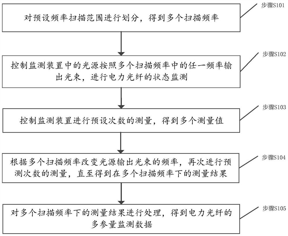
Figure 1 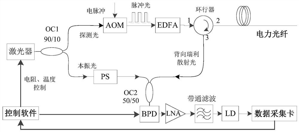
Figure 2 
Figure 3
Abstract
Description
technical field
[0001] The invention relates to the technical field of power optical fiber sensing, in particular to a method, a device and a storage medium for improving the state monitoring accuracy of a power optical fiber. Background technique
[0002] Online monitoring of transmission lines is very important for the safe and stable operation of power grids. At present, the main technical means of online monitoring of transmission lines is to use sensors based on electrical signals, such as wire icing, temperature, micro-meteorology, breeze vibration, leakage current, tower inclination, etc., and return data through wireless networks. However, the operation environment of transmission lines is complex, and the perception and transmission of electrical signals inevitably have technical problems such as electromagnetic interference, and the traffic and communication in some areas are relatively lagging, which limits the popularization and application of online status monit...
Examples
Embodiment 1
[0031] An embodiment of the present invention provides a method for improving the state monitoring accuracy of a power optical fiber, wherein the method is applied to a power fiber state monitoring device, and the power fiber state monitoring device may be based on coherent probe light time domain reflectometer or based on Rayleigh scattering and Bryant Yuan scattering power fiber multi-parameter condition monitoring device, such as figure 1 As shown, the method includes the following steps:
[0032] Step S101: Divide the preset frequency scanning range to obtain a plurality of scanning frequencies.
[0033] In one embodiment, in order to improve the monitoring accuracy of the power fiber state, a frequency scanning method can be used; first, the preset frequency scanning range F[f is set according to the parameters of the light source in the monitoring device. min ,f max ]; The specific frequency scanning range is mainly determined by the performance of the light source. Fo...
Embodiment 2
[0049] Embodiments of the present invention provide a method for improving the state monitoring accuracy of power optical fibers for time-domain reflectometry based on coherent probe light, such as figure 2 shown, can be controlled by the control software in the reflectometer and its implementation can be achieved as follows:
[0050] Step 201: Set the optical frequency scanning range F[f min ,f max ], for example, when RIO's external cavity semiconductor narrow linewidth laser is selected as the sensing light source, the frequency scanning range F is between 25MHz and 250MHz, and F is divided based on the Gaussian distribution to obtain n unequal frequency scanning ranges Interval Δf[Δf 1 ,Δf 2 ,…Δf n ].
[0051] Step 202: Control the current and temperature of the laser, thereby changing the output beam frequency to f min , through the coupler OC 1 Divided into two channels for transmission, one of which is used as probe light, modulates continuous light into pulsed ...
Embodiment 3
[0058] Embodiments of the present invention provide a method for improving the state monitoring accuracy of power optical fibers when used in a power fiber multi-parameter state monitoring device based on Rayleigh scattering and Brillouin scattering, such as Figure 4 shown, you can follow these steps:
[0059] Step 301: Set the frequency scanning range F[f in the control software of the power optical fiber multi-parameter state monitoring device min ,f max ], divide F based on the Gaussian distribution, and obtain n unequal frequency scanning range intervals Δf[Δf 1 ,Δf 2 ,…Δf n ].
[0060] Step 302: Using the laser / modulator integrated platform as the modulation light source, control the frequency and pulse width of the probe light output by the laser / modulator, and adjust the frequency to f min , which is divided into two paths for transmission through the coupler, one path is used as the probe light, coupled into the monitored long-distance power fiber through the opt...