Pneumatic test system of test equipment

A test system and test equipment technology, applied in the field of rail transit, can solve the problems of pneumatic test system space physical structure differences, design difficulty, complexity, heavy workload, poor consistency of test data, etc., to achieve a good batch quality control platform, The physical structure is completely consistent and the effect of reducing the difficulty of redesign

Pending Publication Date: 2021-07-16
CHINA ACADEMY OF RAILWAY SCI CORP LTD +3
View PDF0 Cites 0 Cited by
  • Summary
  • Abstract
  • Description
  • Claims
  • Application Information

AI Technical Summary

Problems solved by technology

[0004] (1) The development of the pneumatic test system is complex and difficult
For the test equipment of different tested products, due to the different pneumatic principles, the pneumatic test system needs to be developed according to the pneumatic principles of the tested products and the pipeline structure, resulting in the difficulty, complexity and workload of the entire design.
[0005] (2) Difficult to assemble and maintain
In the pipeline structure, the pipeline components need to be spliced ​​and assembled to form a certain spatial physical structure, which is difficult to assemble and difficult to maintain in the later stage. Most of the steel pipes in production are customized, which is not conducive to production
[0006] (3) Poor reliability
Due to the large number of pipeline connectors, the probability of air leakage in the pneumatic testing system will increase, which will affect the use of the equipment; during the transportation of the equipment, the vibration will cause the pneumatic testing system of the pipeline structure to loosen and cause a leakage fault. Once a leak occurs, find the leak Points and rectification work are more difficult
[0007] (4) The volume occupied by the pneumatic test system is relatively large, and the maintenance space required in the later period is also relatively large. The space occupied by the pneumatic test system in the entire test equipment increases, resulting in an increase in the overall volume of the test equipment and land resources.
[0008] (5) Since the size of the connection of the pipeline components is not easy to control, there is a certain error in the length dimension after the connection, and there is also an error in the coordinate point in space, resulting in a certain difference in the physical structure of the pneumatic test system space. During the performance test, due to the different air resistance of the pneumatic test system with different structures, the consistency of the test data is poor

Method used


Image

  • Pneumatic test system of test equipment
  • Pneumatic test system of test equipment
  • Pneumatic test system of test equipment

Examples


Embodiment Construction

[0055] In order to have a clearer understanding of the technical features, purposes and effects of the present invention, the specific implementation manners of the present invention will now be described with reference to the accompanying drawings.

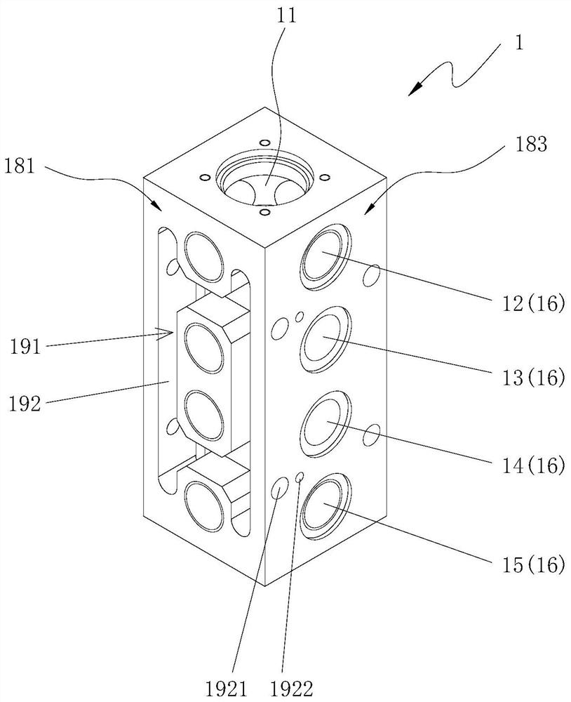
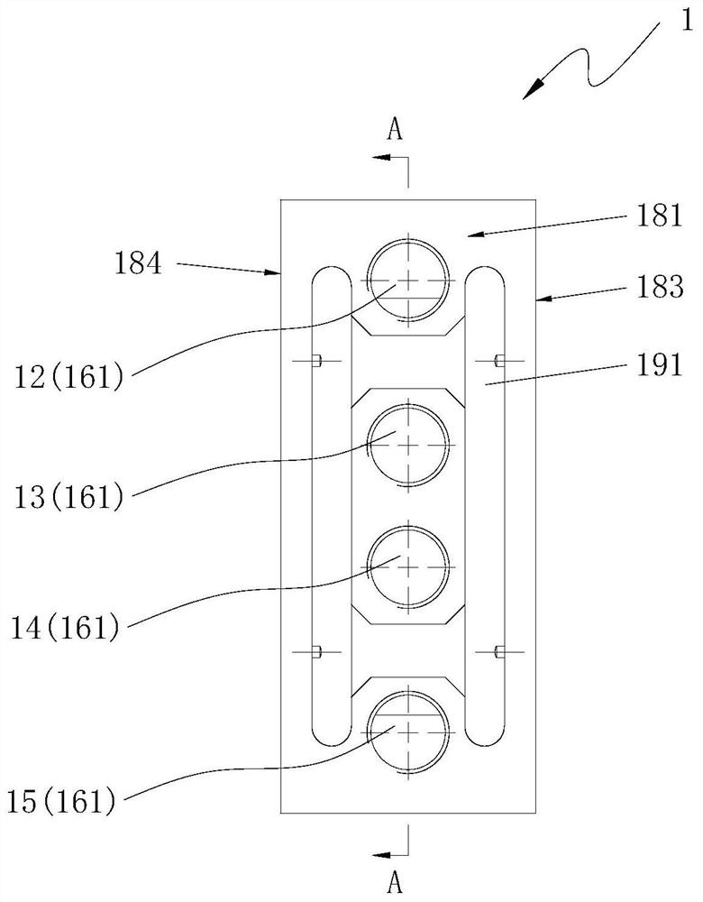
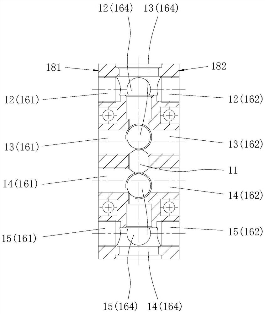
[0056] Such as Figure 1 to Figure 17 As shown, the present embodiment provides a pneumatic test system for test equipment, including at least one basic modular unit 100 . Each basic module unit 100 includes a valve seat 1 , a first solenoid valve head 21 and a second solenoid valve head 22 , and a main channel 11 is opened in the valve seat 1 through its first end surface and its second end surface. In the valve seat 1, from the first end to the second end, there are sequentially arranged the first layer of channels 12, the second layer of channels 13, the third layer of channels 14 and the fourth layer of channels 15, the first layer of channels 12. The second channel 13 , the third channel 14 and the fourth channel 15 each in...


PUM


Abstract

The invention relates to a pneumatic test system of test equipment. The pneumatic test system comprises at least one basic module unit, each basic module unit comprises a valve seat, a first electromagnetic valve head and a second electromagnetic valve head, and a main channel is formed in each valve seat. A first-layer channel, a second-layer channel, a third-layer channel and a fourth-layer channel which are arranged at intervals are arranged in the valve seat, and each of the first-layer channel, the second-layer channel, the third-layer channel and the fourth-layer channel comprises at least one branch channel. The first electromagnetic valve head is fixedly arranged on the first end face of the valve seat and can communicate or disconnect the first-layer channel and the second-layer channel, and the second electromagnetic valve head is fixedly arranged on the second end face of the valve seat and can communicate or disconnect the third-layer channel and the fourth-layer channel. The pneumatic test system of the test equipment is high in universality and expandability, compact in structure, small in size and convenient to assemble and maintain, and the test consistency of batch application of the test equipment is obviously improved.

Description

technical field [0001] The invention relates to the technical field of rail transportation, in particular to a pneumatic test system of test equipment. Background technique [0002] In the field of railway vehicles, when the products on the train are newly manufactured or overhauled, the performance or function of the product must be tested by special test equipment, and the product can be loaded only after passing the test. For the related components of the air brake system, the pneumatic test system is one of the important components of its test equipment. The pneumatic test system can simulate the pneumatic operating environment required by the tested product, such as air pressure control, flow control, and direction control. And pressure acquisition and other related parameters, so as to accurately evaluate the product performance or function. [0003] The pneumatic test system of the existing test equipment is basically a pipeline structure, which is realized through p...

Claims


Application Information

Patent Timeline
Patent Type & Authority Applications(China)
IPC IPC(8): G01M13/00
CPCG01M13/00
Inventor 白旺旺康旭王苏敬钱晨刘潇孙霖高文灏索建国余欲为
Owner CHINA ACADEMY OF RAILWAY SCI CORP LTD
Why Eureka
Try Eureka