
Visual image type fire detection alarm device

A fire detection and alarm device technology, applied in fire alarms, fire alarms that rely on radiation effects, fire alarms that rely on smoke/gas effects, etc., can solve camera blurring, unclear images, loss of life and property and other problems, to achieve the effect of monitoring intuitively and ensuring the shooting effect

Pending Publication Date: 2021-07-16
王大卫
View PDF0 Cites 2 Cited by
  • Summary
  • Abstract
  • Description
  • Claims
  • Application Information

AI Technical Summary

Problems solved by technology

[0002] With the increase of fire and electricity consumption in modern households, the frequency of household fires is getting higher and higher. Once a household fire occurs, it is easy to have untimely fighting, lack of fire extinguishing equipment, panic of the people present, and slow escape. Eventually lead to heavy loss of life and property, so the use of fire detection and alarm devices is becoming more and more extensive. Among them, the visual image fire detection and alarm devices can not only detect fires, but also perform real-time monitoring, making the monitoring more intuitive, but the existing When the image-based fire detection and alarm device broadcasts the fire image, a large amount of smoke and dust generated by the fire will cover the monitoring camera, which will cause the camera to become blurred. After the camera becomes blurred, the broadcast image will not be clear enough, and the existing image Most permanent fire detection and alarm devices are directly fixed on high places, and the shooting angle cannot be adjusted, so it is impossible to conveniently shoot the source of the fire. Therefore, we propose a visual image type fire detection and alarm device

Method used


Image

  • Visual image type fire detection alarm device
  • Visual image type fire detection alarm device
  • Visual image type fire detection alarm device

Examples


Embodiment Construction

[0027] The following will clearly and completely describe the technical solutions in the embodiments of the present invention with reference to the accompanying drawings in the embodiments of the present invention. Obviously, the described embodiments are only some, not all, embodiments of the present invention. Based on the embodiments of the present invention, all other embodiments obtained by persons of ordinary skill in the art without making creative efforts belong to the protection scope of the present invention.

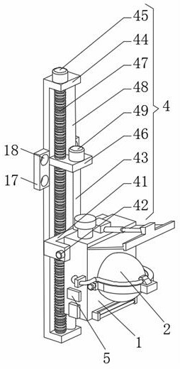
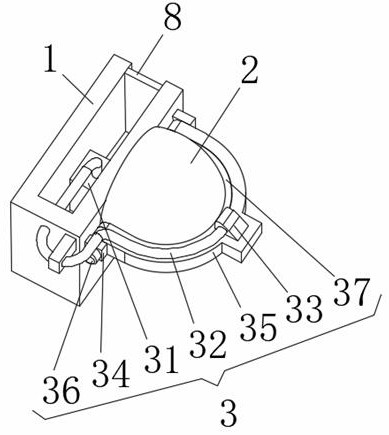
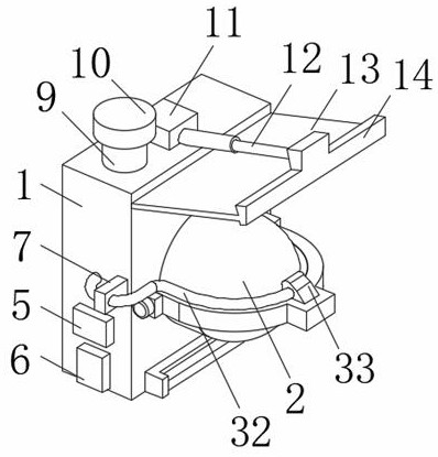
[0028] see Figure 1-4 , the present embodiment provides a technical solution: a visual image type fire detection and alarm device, including an installation box 1 and a cleaning assembly 3;

[0029] Installation box 1: camera 2 is installed on the front side, and the shape of the outer protective cover of camera 2 is hemispherical, and the rear end of installation box 1 is equipped with adjustment assembly 4, and adjustment assembly 4 comprises U-shaped frame...


PUM


Abstract

The invention discloses a visual image type fire detection alarm device which comprises: a mounting box and a cleaning assembly. A camera is installed on the front side face of the mounting box, a protective cover outside the camera is hemispherical, and an adjusting assembly is installed at the rear end of the mounting box; the cleaning assembly comprises a water pump, a water conveying pipe and a spray head, the water pump is mounted in the mounting box, a through hole is formed in the left side face of the mounting box, the water conveying pipe is fixed in the through hole, the rear end of the water conveying pipe is fixed in a water outlet valve of the water pump, and the spray head is mounted at the front end of the water conveying pipe; the cleaning assembly is arranged to clean the camera; the device further comprises a PLC and a smoke sensor, the PLC and the smoke sensor are both installed on the left side face of the mounting box, the input end of the PLC is electrically connected with the output end of an external power source, the camera can be conveniently cleaned, and a fire source can be conveniently shot.

Description

technical field [0001] The invention relates to the technical field of alarm devices, in particular to a visual image type fire detection and alarm device. Background technique [0002] With the increase of fire and electricity consumption in modern households, the frequency of household fires is getting higher and higher. Once a household fire occurs, it is easy to have untimely fighting, lack of fire extinguishing equipment, panic of the people present, and slow escape. Eventually lead to heavy loss of life and property, so the use of fire detection and alarm devices is becoming more and more extensive. Among them, the visual image fire detection and alarm devices can not only detect fires, but also perform real-time monitoring, making the monitoring more intuitive, but the existing When the image-based fire detection and alarm device broadcasts the fire image, a large amount of smoke and dust generated by the fire will cover the monitoring camera, which will cause the cam...

Claims


Application Information

Patent Timeline
IPC IPC(8): G08B17/10G08B17/12H04N5/225H04N5/232F16M11/18B08B3/02
CPCG08B17/10G08B17/125F16M11/18B08B3/02H04N23/52H04N23/51H04N23/695
Inventor 王大卫
Owner 王大卫
Learn More