
Clamping ring chamfering equipment

A chamfering and snap ring technology, which is applied in metal processing equipment, grinding/polishing equipment, grinding machines, etc., can solve the problems of different chamfering sizes and different states at both ends, so as to reduce the transfer process and improve production efficiency , Improve the effect of chamfering accuracy

Pending Publication Date: 2021-07-20
ZHEJIANG MEILI HIGH TECH
View PDF0 Cites 2 Cited by
  • Summary
  • Abstract
  • Description
  • Claims
  • Application Information

AI Technical Summary

Problems solved by technology

[0004] The purpose of the present invention is to overcome the problem that the state of the two ends of the snap ring in the prior art is different, there are sag surfaces and burr surfaces, and when the existing tooling chamfers the snap ring, there are problems of different chamfer sizes, and provides a snap ring The chamfering equipment has simple structure and convenient operation. The height of the left and right tooling can be adjusted separately, so that the chamfering on both sides can be carried out continuously, which improves the production efficiency

Method used


Image

  • Clamping ring chamfering equipment
  • Clamping ring chamfering equipment
  • Clamping ring chamfering equipment

Examples


Embodiment Construction

[0022] The present invention will be further described below in conjunction with the accompanying drawings and specific embodiments.

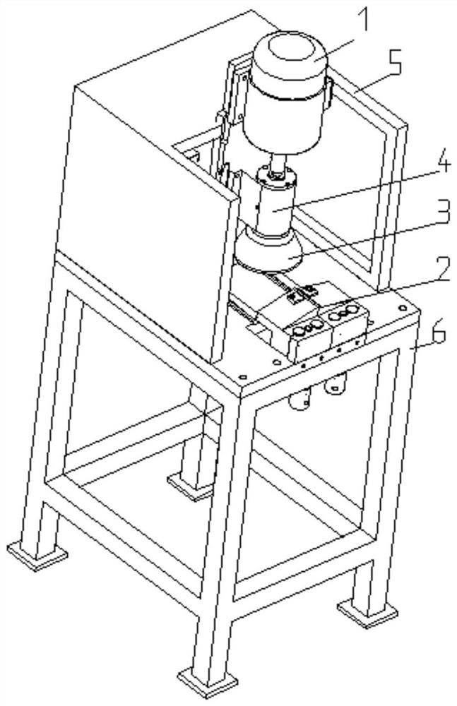
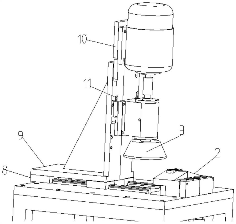
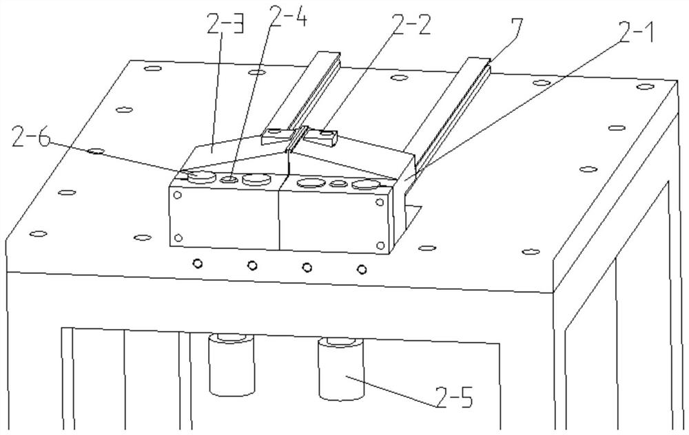
[0023] exist figure 1 , figure 2 , image 3 , Figure 4 and Figure 5 In the shown embodiment, a clasp ring chamfering device of the present invention includes a driving motor 1, a grinding wheel 3, two tooling 2 capable of independently adjusting the height and a workbench 6, and the driving motor is fixedly arranged on the motor bracket , the motor bracket is slidingly connected to the workbench, the output end of the driving motor is connected to a rotating shaft, the output end of the motor is connected to the rotating shaft through a coupling, the grinding wheel is fixedly connected to the rotating shaft, the The tooling is fixedly arranged on the workbench, and the heights of the two toolings are respectively adjusted according to the chamfering parameters at both ends of the snap ring, and the motor bracket slides to drive the grind...


PUM


Abstract

The invention discloses clamping ring chamfering equipment. The clamping ring chamfering equipment comprises a driving motor, a grinding wheel, two tools and a workbench, wherein the heights of the two tools can be independently adjusted, the driving motor is fixedly arranged on a motor support, the motor support is slidably connected with the workbench, the output end of the driving motor is connected with a rotating shaft, the grinding wheel is fixedly connected with the rotating shaft, the tools are fixedly arranged on the workbench, the heights of the two tools are adjusted according to chamfering parameters of the two ends of a clamping ring, and the motor support slides to drive the grinding wheel to slide to chamfer the clamping ring. According to the clamping ring chamfering equipment, the tools can be independently adjusted, the chamfering operation of a single part can be completed at a time, the transfer procedure and the additional tool adjusting procedure are reduced, and the production efficiency is improved; and the chamfering mode that parts are fixed and the grinding wheel moves is adopted to solve the problem that the chamfering size is not stable due to movement of the parts, and meanwhile operation convenience of workers is improved.

Description

technical field [0001] The invention relates to the technical field of snap ring chamfering, in particular to a snap ring chamfering equipment. Background technique [0002] Most of the existing snap rings need to be chamfered on both ends and four sides. The existing chamfering machine is equipped with one piece of chamfering tooling on both sides. Chamfering, manually push the tooling during chamfering, so that the parts enter the grinding wheel for chamfering. When chamfering with this chamfering machine, because the chamfering parameters on the left and right sides are inconsistent, all parts need to be chamfered on one side before adjusting the tooling to chamfer the other side, adding a transfer process, and the current and subsequent batches are of the same type When removing parts, the tooling needs to be readjusted, which is inefficient. Manually push the tooling. During the process of pushing the tooling, the parts may move, the size of the chamfer is unstable, a...

Claims


Application Information

Patent Timeline
Patent Type & Authority Applications(China)
IPC IPC(8): B24B9/00B24B41/06B24B41/04B24B41/02B24B47/12
CPCB24B9/00B24B41/02B24B41/04B24B41/06B24B47/12
Inventor 王君谦杨勇王苏成
Owner ZHEJIANG MEILI HIGH TECH
Learn More