Check patentability & draft patents in minutes with Patsnap Eureka AI!

A Brake Difference Monitoring System Based on Pneumatic Brake Response Time

A technology of response time and monitoring system, applied in the direction of braking safety system, etc., can solve the problems of poor deviation control effect and high cost of improvement, and achieve the effect of eliminating potential safety hazards and reducing the amount of calculation.

Active Publication Date: 2022-03-29
湖南三一车身有限公司
View PDF7 Cites 0 Cited by
  • Summary
  • Abstract
  • Description
  • Claims
  • Application Information

AI Technical Summary

Problems solved by technology

[0007] The invention provides a braking difference monitoring system based on the response time of the air brake, which is used to solve the defects of poor tracking control effect and high improvement cost in the existing braking technology, so as to achieve high braking difference at low cost Reliability Monitoring

Method used


Image

  • A Brake Difference Monitoring System Based on Pneumatic Brake Response Time
  • A Brake Difference Monitoring System Based on Pneumatic Brake Response Time
  • A Brake Difference Monitoring System Based on Pneumatic Brake Response Time

Examples


Embodiment 1

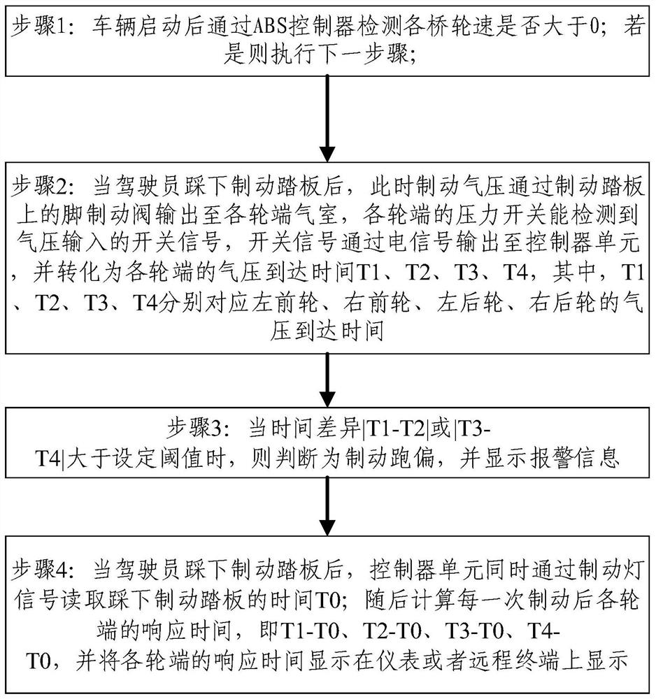
[0046] Such as figure 2 As shown, in order to ensure the consistency of left and right after braking, the lateral left and right difference braking difference monitoring method includes the following steps:

[0047] Step 1: After the vehicle is started, check whether the wheel speed of each axle is greater than 0 through the ABS controller; if so, execute the next step; otherwise, stop executing the program and manually check for hardware problems;

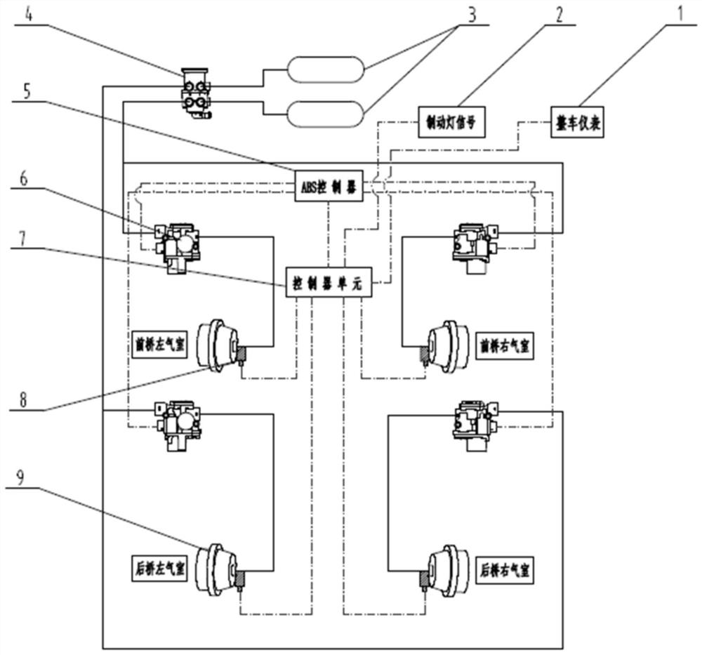
[0048] Step 2: When the driver depresses the brake pedal, the brake air pressure is output to the air chamber at each wheel end through the foot brake valve on the brake pedal, and the pressure switch at each wheel end can detect the switch signal of the air pressure input. The switch signal is output to the controller unit through an electrical signal, and converted into the air pressure arrival time T1, T2, T3, T4 at each wheel end, where T1, T2, T3, T4 correspond to the left front wheel, right front wheel, and left rear wheel ...

Embodiment 2

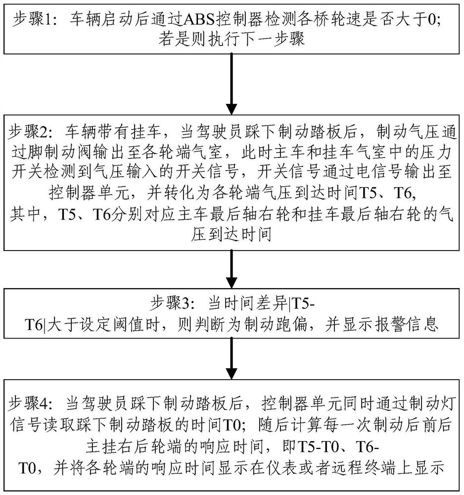
[0060] Such as image 3 As shown, in order to ensure the consistency of the main suspension after braking, the braking difference monitoring method of the front and rear differences of the main suspension includes the following steps:

[0061] Step 1: After the vehicle is started, check whether the wheel speed of each axle is greater than 0 through the ABS controller; if so, execute the next step; otherwise, stop executing the program and manually check for hardware problems;

[0062] Step 2: The vehicle has a trailer (for example: truck or tractor, forklift). When the driver steps on the brake pedal, the brake air pressure is output to the air chamber at the end of each wheel through the foot brake valve. At this time, the main vehicle and the trailer The pressure switch in the air chamber detects the switch signal of the air pressure input, and the switch signal is output to the controller unit through the electrical signal, and converted into the arrival time T5 and T6 of t...


PUM


Abstract

The present invention provides a braking difference monitoring system based on the response time of the air brake. A pressure switch is installed between the air pipe joint at the air inlet of each wheel end air chamber and the air pipe. It also includes a processor for performing the following monitoring methods: Obtain the operating state of the brake pedal in real time during driving; when the operating state of the brake pedal is the start state, obtain the response time of each wheel end pressure switch and calculate the brake pedal according to the difference in the response time of each wheel end pressure switch If the brake offset is greater than the preset threshold, it will be judged as a brake difference; the response time of the pressure switch at each wheel end is from the start moment of the brake pedal to the pressure switch at each wheel end Time interval at which brake air pressure input is detected. The monitoring system can effectively judge whether there is a braking difference in the vehicle, and can also calculate the response time of the wheel braking at each wheel end and display it on the instrument, and is low in cost and easy to maintain.

Description

technical field [0001] The invention relates to the technical field of vehicle braking, in particular to a braking difference monitoring system based on air braking response time. Background technique [0002] Braking difference is a long-standing problem for commercial vehicles at home and abroad, but in the daily driving process, drivers can rarely find out whether there is a braking difference phenomenon unless the deviation is serious, and heavy trucks have higher requirements for safety. The demand for real-time detection of deviation is obviously stronger. At present, domestic commercial vehicles or large transport vehicles basically detect vehicle deviation based on pressure. [0003] For example, Chinese patent CN201510471785.5 discloses a vehicle braking difference control method, system and vehicle, which includes a position sensor and a pressure sensor, by monitoring the length of the piston rod of the brake cylinder or the pressure in the cylinder, and converting...

Claims


Application Information

Patent Timeline
Patent Type & Authority Patents(China)
IPC IPC(8): B60T17/22
CPCB60T17/22
Inventor 梁祥安商艳春甘凯宁
Owner 湖南三一车身有限公司
Features
  • R&D
  • Intellectual Property
  • Life Sciences
  • Materials
  • Tech Scout
  • Unparalleled Data Quality
  • Higher Quality Content
  • 60% Fewer Hallucinations
Learn More